
A clearer picture.
Denture stages, dental radiographs, clinical photographs, histology and labelled diagrams. Explore the detail, connect it to a chapter and test what you can explain.
Take your anatomy off the page.
Explore interactive head and neck, body, tooth and dentition models. Rotate, reveal and click to learn.
Complete denture stages
Follow a clinical example through assessment, impressions, wax trial and processing. Neutral-zone recording and palatograms are additional techniques used in this case; they are not mandatory stages for every denture.
Edentulous ridges: the denture foundation
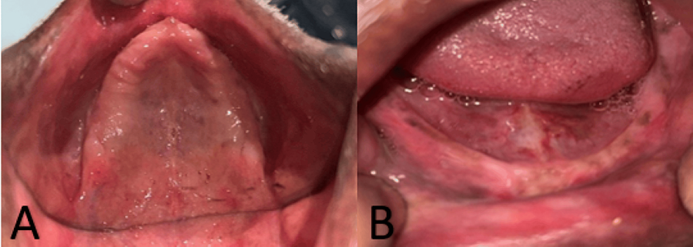
Upper (A) and lower (B) edentulous ridges in the source case. Relate the visible anatomy to the denture-bearing tissues described in the chapter.
Panel key
- A
- Maxillary edentulous ridge and palate.
- B
- Mandibular edentulous ridge.
Refining Complete Dentures — figure 2 · Rucha Chiddarwar, Anjali Bhoyar, Surekha A. Dubey, Mithilesh M. Dhamande and Sheetal R. Khubchandani · CC BY 4.0. Original published figure reproduced without alteration; panel letters and labels retained.
Primary impressions for complete dentures
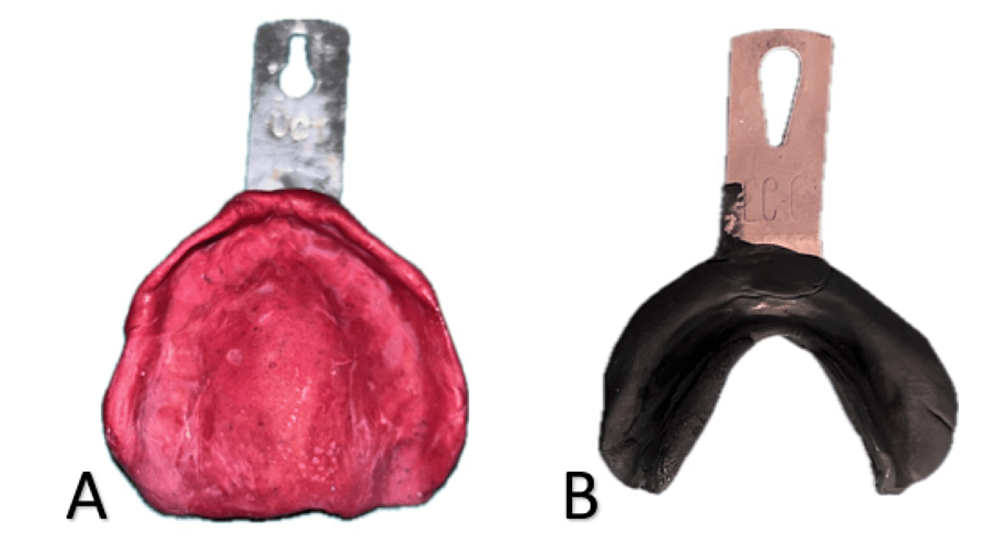
Upper and lower preliminary records from the same case. The materials illustrate this author’s technique rather than a required material choice for every patient.
Panel key
- A
- Maxillary impression in impression compound.
- B
- Mandibular impression using an admix material.
Refining Complete Dentures — figure 3 · Rucha Chiddarwar, Anjali Bhoyar, Surekha A. Dubey, Mithilesh M. Dhamande and Sheetal R. Khubchandani · CC BY 4.0. Original published figure reproduced without alteration; panel letters and labels retained.
Definitive impressions: upper and lower arches
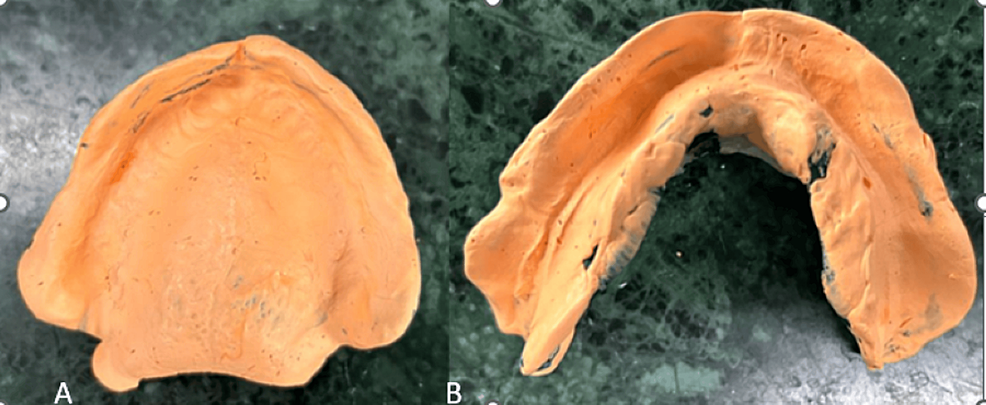
Final impressions from the source case. Compare their coverage and borders with the preliminary records, alongside the chapter’s impression checks.
Panel key
- A
- Maxillary definitive impression.
- B
- Mandibular definitive impression.
Refining Complete Dentures — figure 4 · Rucha Chiddarwar, Anjali Bhoyar, Surekha A. Dubey, Mithilesh M. Dhamande and Sheetal R. Khubchandani · CC BY 4.0. Original published figure reproduced without alteration; panel letters and labels retained.
Neutral-zone record and putty index
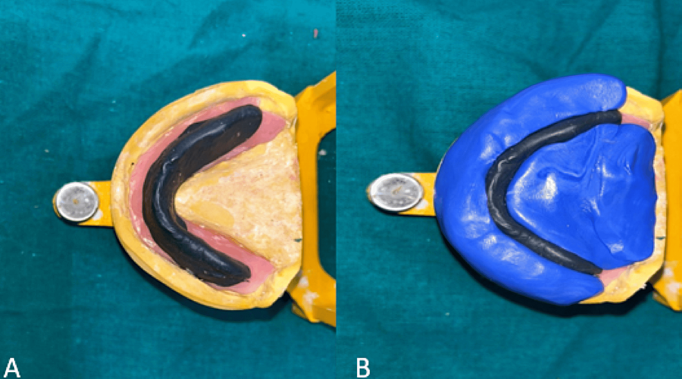
An additional functional recording technique used for the resorbed-ridge case. It guides tooth position and is not a compulsory stage for every complete denture.
Panel key
- A
- Neutral-zone record on the mandibular base.
- B
- Putty index made around the record.
Refining Complete Dentures — figure 5 · Rucha Chiddarwar, Anjali Bhoyar, Surekha A. Dubey, Mithilesh M. Dhamande and Sheetal R. Khubchandani · CC BY 4.0. Original published figure reproduced without alteration; panel letters and labels retained.
Wax try-in: trial tooth arrangement
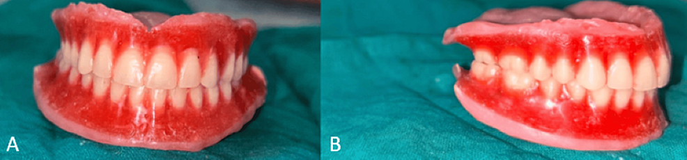
The trial dentures still have wax bases. Connect the tooth arrangement with checks of appearance, speech, jaw relationship and patient preferences before processing.
Panel key
- A–B
- Two views of the trial tooth arrangement in wax.
Refining Complete Dentures — figure 6 · Rucha Chiddarwar, Anjali Bhoyar, Surekha A. Dubey, Mithilesh M. Dhamande and Sheetal R. Khubchandani · CC BY 4.0. Original published figure reproduced without alteration; panel letters and labels retained.
Palatogram: checking tongue contact during speech
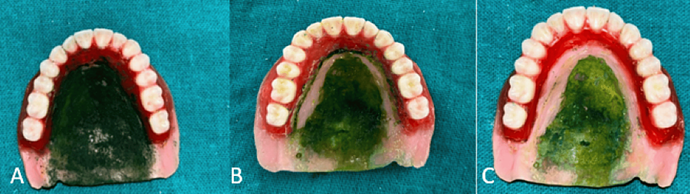
A specialist speech assessment used in this case. The palatal marking records tongue contact; it is separate from checking the denture’s fitting surface.
Panel key
- A
- Marking applied to the palatal surface.
- B
- Contact pattern with the initial contour.
- C
- Pattern after selective palatal correction.
Refining Complete Dentures — figure 7 · Rucha Chiddarwar, Anjali Bhoyar, Surekha A. Dubey, Mithilesh M. Dhamande and Sheetal R. Khubchandani · CC BY 4.0. Original published figure reproduced without alteration; panel letters and labels retained.
Processing and the finished acrylic dentures
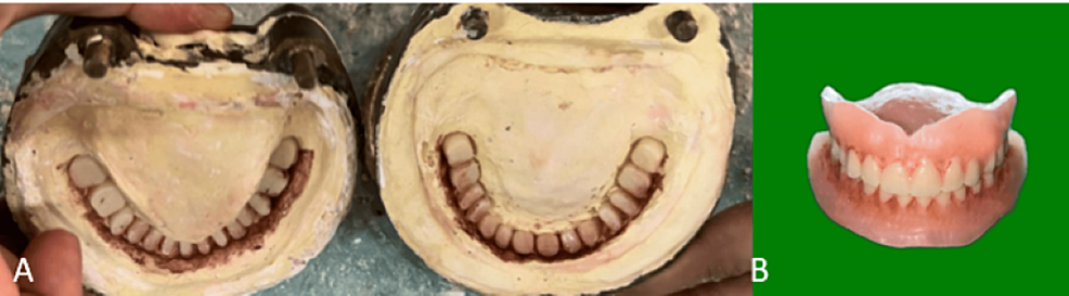
The source illustrates aesthetic characterisation during processing and the completed dentures. This is one case example, not a photograph of every laboratory step.
Panel key
- A
- Characterisation stains placed in the mould.
- B
- Finished dentures with characterised acrylic.
Refining Complete Dentures — figure 8 · Rucha Chiddarwar, Anjali Bhoyar, Surekha A. Dubey, Mithilesh M. Dhamande and Sheetal R. Khubchandani · CC BY 4.0. Original published figure reproduced without alteration; panel letters and labels retained.
Dental radiographs in practice
Study caries, periodontal bone loss, apical change, root fillings, a separated instrument and a lateral cephalogram. Describe what is visible, then connect it with the clinical findings and the relevant chapter.
Proximal caries in primary molars
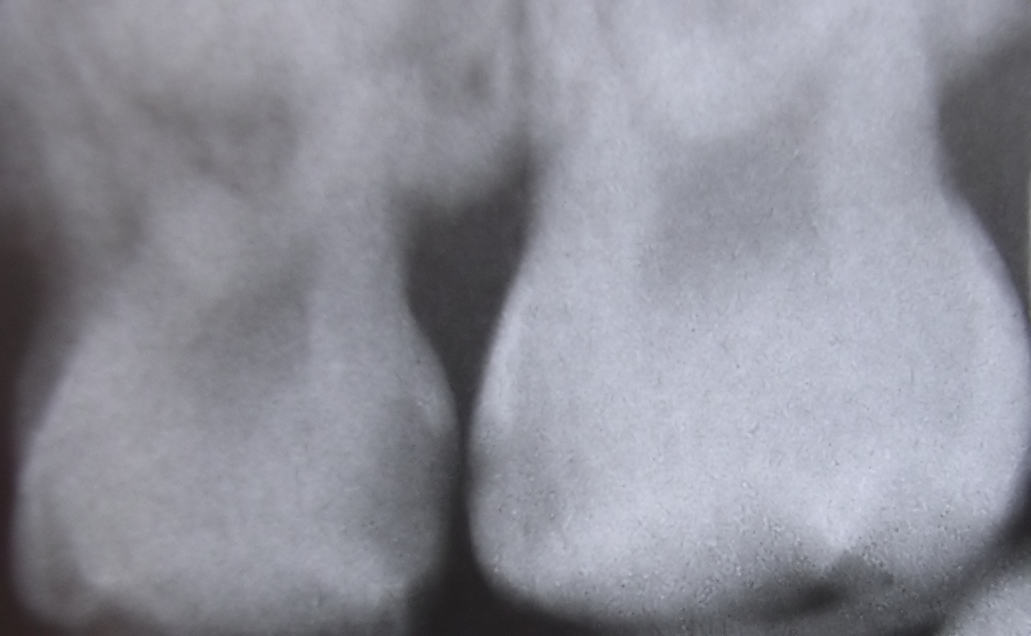
The source identifies interproximal caries between upper primary molars. Describe the radiolucent areas beneath the contact, then assess activity and cavitation clinically.
Interproximaldecayfiltered08-16-2006.jpg · Dozenist · CC BY-SA 3.0. Source author’s Neat Image processing retained. No additional image changes.
Impacted third molar beside distal second-molar caries
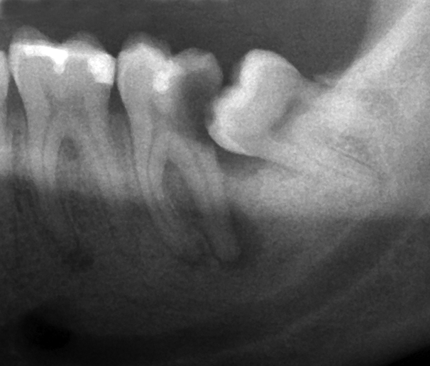
The source identifies caries on the second molar beside an impacted lower third molar. Describe the tooth positions and adjacent surface before deciding the clinical significance.
Wisdom tooth causing dental caries.png · Coronation Dental Specialty Group · CC BY-SA 3.0. Image reproduced without alteration; original marks and any embedded credits retained.
Periodontal bone loss on a periapical radiograph
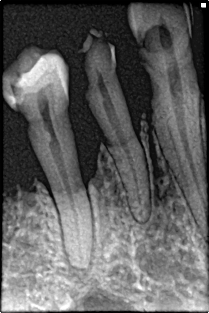
Trace the reduced bone height and irregular contour between the teeth. Correlate with full periodontal charting; this single image cannot establish the patient’s complete stage and grade.
Bone loss in periapical xray.jpg · Shaimaa Abdellatif · CC BY-SA 4.0. Image reproduced without alteration; original marks and any embedded credits retained.
Separated endodontic instrument: a complication example
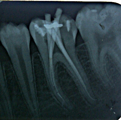
The author identifies a separated instrument in the mesial root canal. Compare the short radiopaque fragment with the longer instruments; this illustrates a complication, not an ideal treatment endpoint.
Broken endodontic file in mesial root canal.jpg · Dr.mohan m.muthal · CC BY-SA 4.0. Image reproduced without alteration; original marks and any embedded credits retained.
Apical radiolucency around a premolar
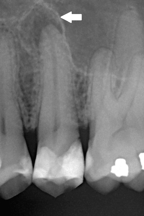
The original arrow marks the radiolucency described as apical periodontitis in the source. Relate this finding to symptoms and pulp tests rather than assigning a diagnosis from the shadow alone.
Chronic apical periodontitis.jpg · Michele Gardini; original arrow annotation by Lesion · CC BY-SA 3.0. Image reproduced without alteration; original marks and any embedded credits retained.
Root-filled molar: trace the visible canals
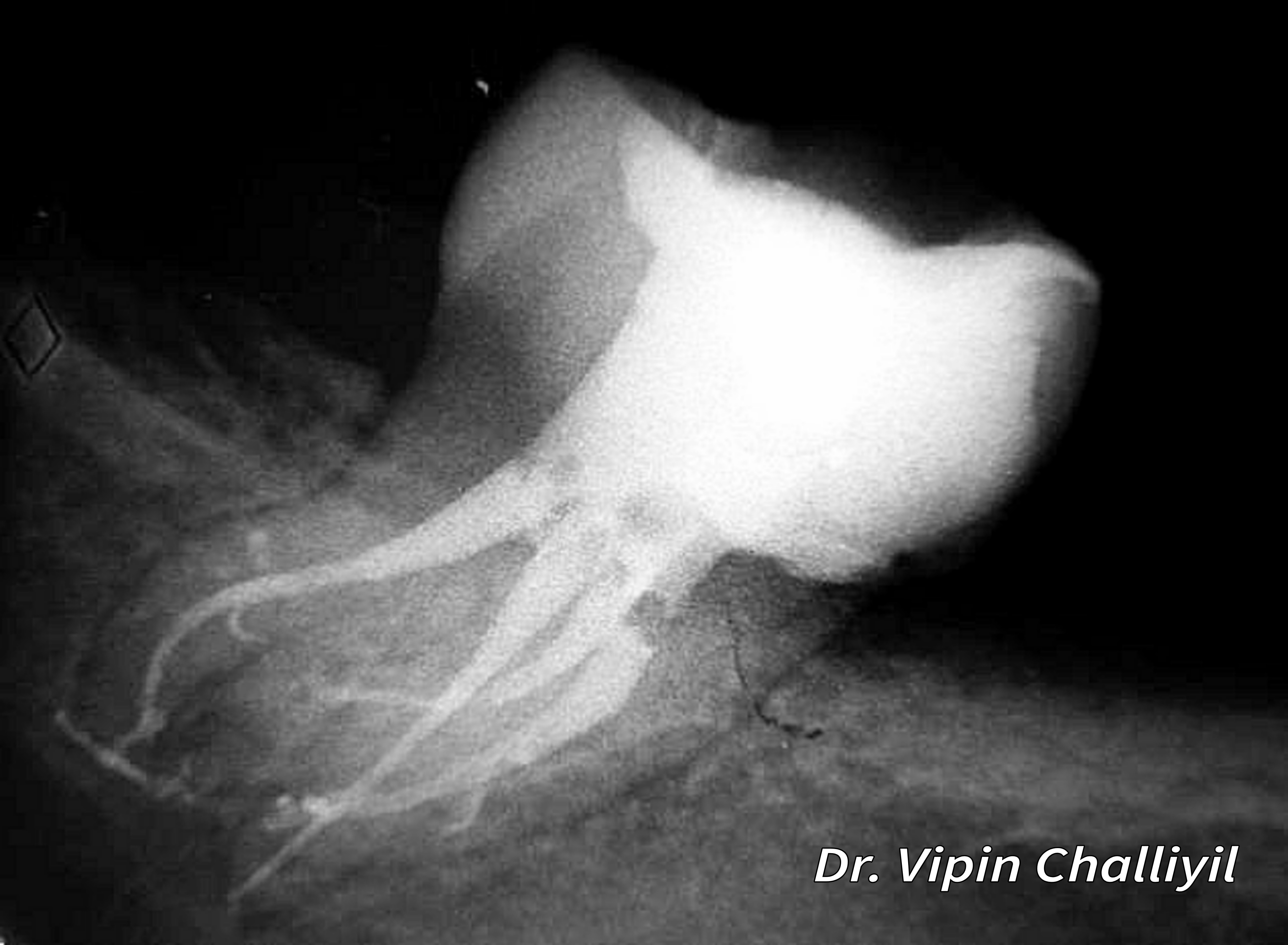
Follow the radiopaque root fillings and the surrounding root outlines. The image illustrates canal anatomy after treatment; radiographic appearance alone does not establish disinfection or healing.
Root canal treatment of lone standing molar.jpg · Challiyan (Dr Vipin Challiyil) · CC BY-SA 4.0. Image reproduced without alteration; original marks and any embedded credits retained.
Lateral cephalogram: orient the orthodontic record
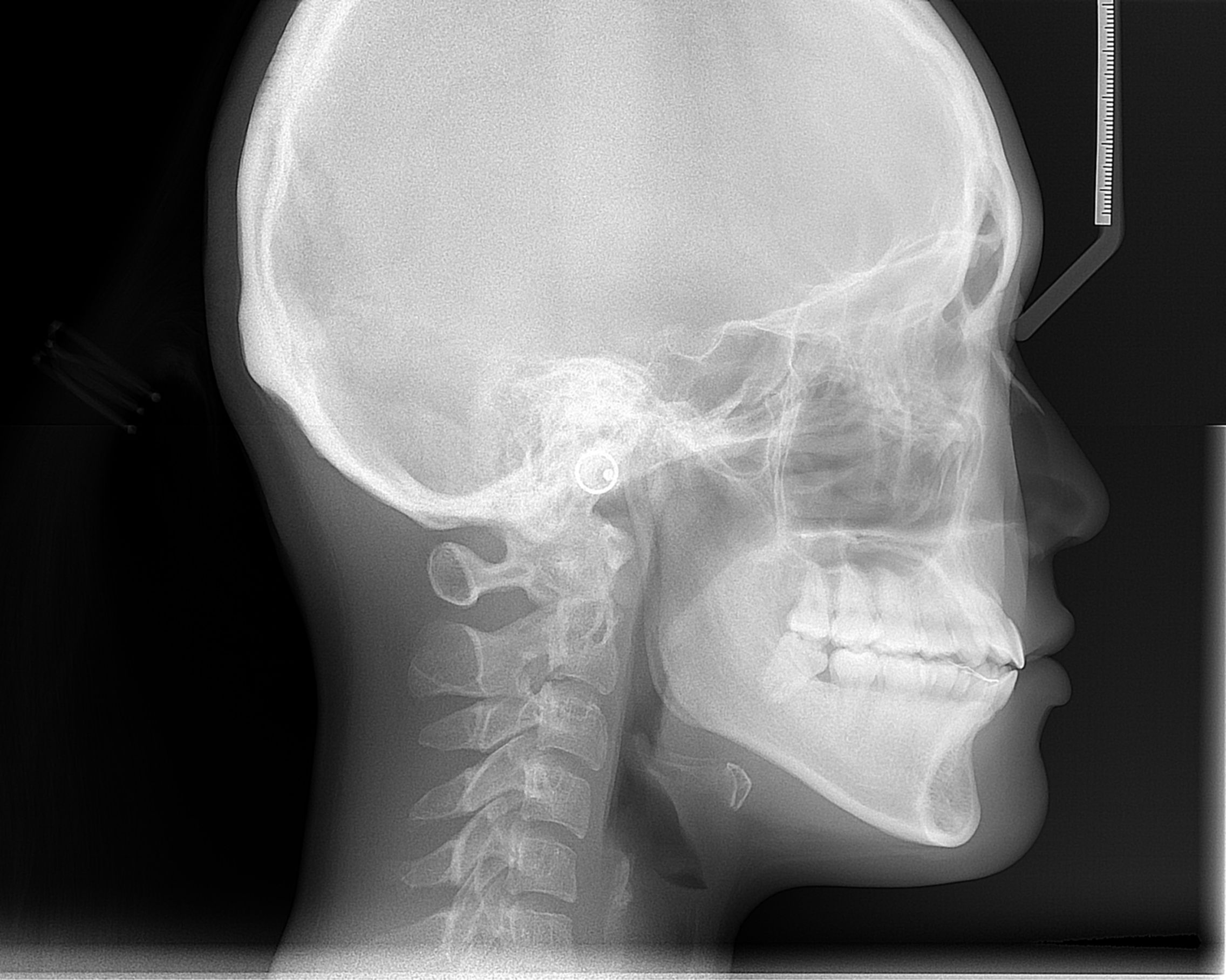
Orient the cranial base, jaws, incisors and soft-tissue outline. Use this as an anatomy example alongside the chapter on justification and interpretation of orthodontic records.
Cephalometric radiograph.JPG · ANUG · CC BY-SA 4.0. Image reproduced without alteration; original marks and any embedded credits retained.
Bridges
Compare support, retainers and design in conventional, cantilever, resin-bonded and implant bridges.
Conventional three-unit fixed-fixed bridge on a cast
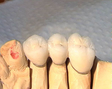
A three-unit posterior bridge on a laboratory cast: two crown retainers flank a central pontic. This small photograph shows tooth support but does not identify the cement or detailed pontic–ridge contact.
Conventional three-unit fixed-fixed bridge on a cast · RosarioVanTulpe · CC BY-SA 3.0. Downloaded current Commons file unchanged.
Canine-supported crown-retained zirconia cantilever
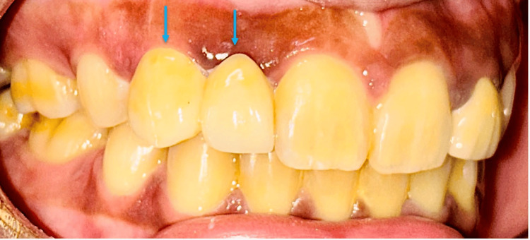
A zirconia cantilever replacing the upper right lateral incisor from a prepared canine crown, shown after cementation. The original blue arrows identify the two connected units. The fitting surface is not visible.
Canine-supported crown-retained zirconia cantilever · Madhurima Sharma, Rohit Nandan, Rohit Sharma, Shalabh Kumar, Akash Gopi, Raina Agarwal, Samra Ashraf, Srijita Mahata and Papan Barman · CC BY 4.0. Original image and blue arrows preserved; no added labels. Original publication.
Two-wing Maryland bridge, rear view
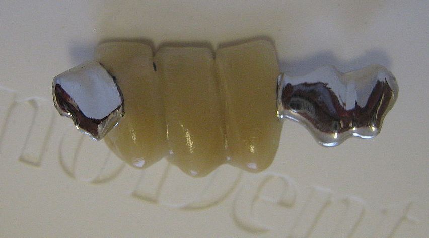
A detached lower anterior Maryland bridge with three pontic units and metal retainers at both ends. This is a multi-pontic, two-wing example; it should not be labelled as the usual single-pontic design.
Two-wing Maryland bridge, rear view · Richard Avery; current crop by Partynia · CC BY-SA 3.0. Downloaded existing Commons crop unchanged.
Anterior resin-bonded bridge with seating hooks
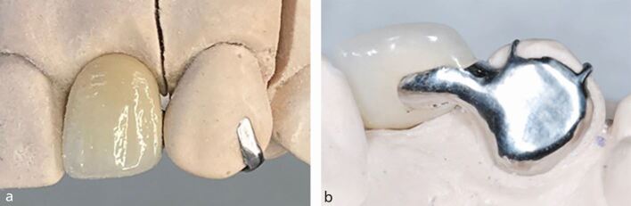
Anterior resin-bonded bridge views demonstrating temporary seating hooks for accurate placement during cementation. Panel b clearly shows one broad metal wing; the number of hooks does not represent the number of retainers.
Anterior resin-bonded bridge with seating hooks · Stephanie King, Banoo Sood and Martin P. Ashley · CC BY 4.0. Original complete labelled figure preserved. Original publication.
Posterior single-wing resin-bonded bridge on a cast
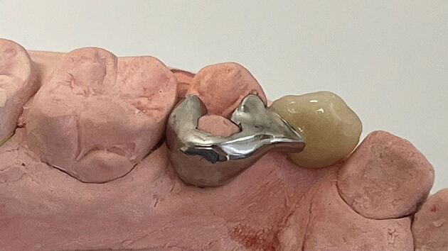
A posterior resin-bonded bridge with one non-perforated wing, proximal wrap-around, rest seats and a substantial connector to the pontic. This cast view illustrates the retainer design; it does not show the clinical bonding interface.
Posterior single-wing resin-bonded bridge on a cast · Stephanie King, Banoo Sood and Martin P. Ashley · CC BY 4.0. Original complete image preserved. Original publication.
Implant-supported bridge on three implants, laboratory view
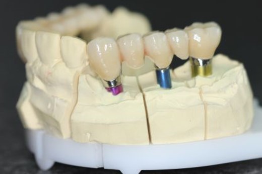
Laboratory view of an implant-supported bridge on three implant components. The coloured components make the support points visible; this is a cast, so the image does not show implants within bone.
Implant-supported bridge on three implants, laboratory view · Drmscmuc · CC BY-SA 4.0. Original complete image preserved.
Partial denture designs
Connect Kennedy classes, connectors and clasp assemblies with real frameworks and teaching models.
Lingual bar on a mandibular teaching model
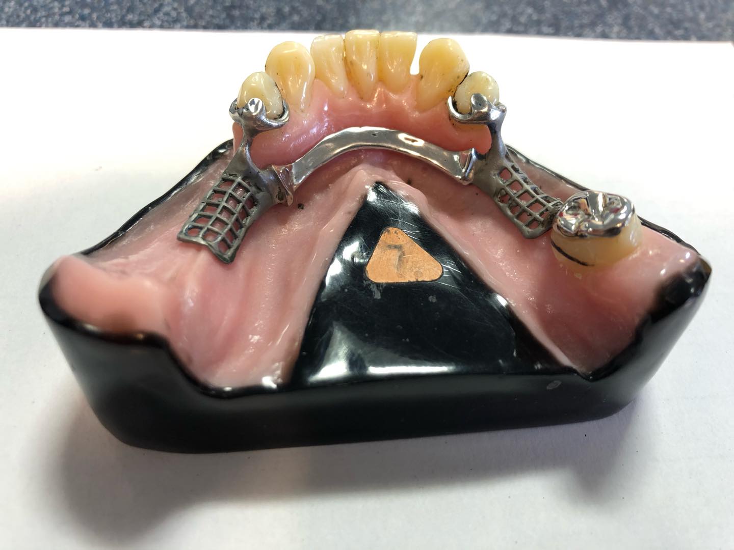
Actual photographed teaching framework from Dundee Dental School. The bar lies below the lingual surfaces of the anterior teeth. Posterior saddle meshwork and clasp/rest assemblies are visible; one side includes a remaining posterior tooth and the other a free-end ridge. Alloy, exact dimensions, clinical suitability and formal Kennedy classification are not documented by the source.
Lingual bar on a mandibular teaching model · MookieSutida · CC BY-SA 4.0. None; original photograph downloaded.
Lingual plate on a mandibular teaching model
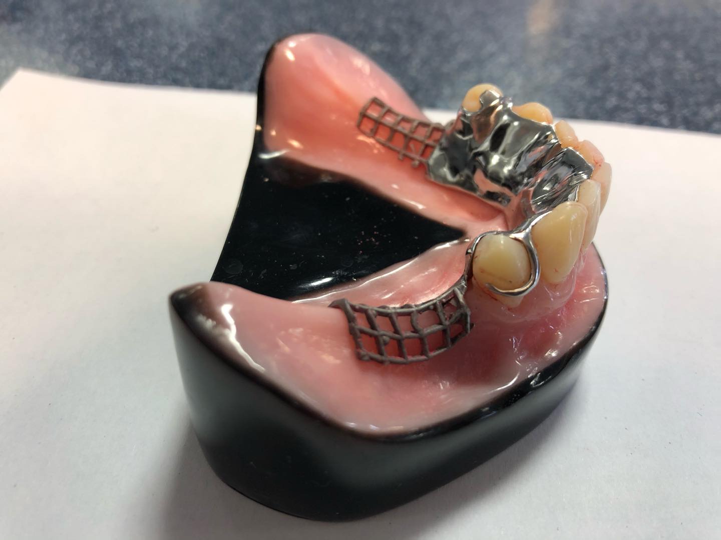
Actual photographed Dundee Dental School teaching framework. The lingual plate extends onto the lingual surfaces of the remaining teeth, unlike the separate lingual bar image. Bilateral posterior free-end ridges and meshwork are visible. This shows connector coverage, not a universal prescription; source does not verify Co-Cr alloy or dimensions.
Lingual plate on a mandibular teaching model · MookieSutida · CC BY-SA 4.0. None; original photograph downloaded.
Maxillary metal framework with an anteroposterior palatal connector
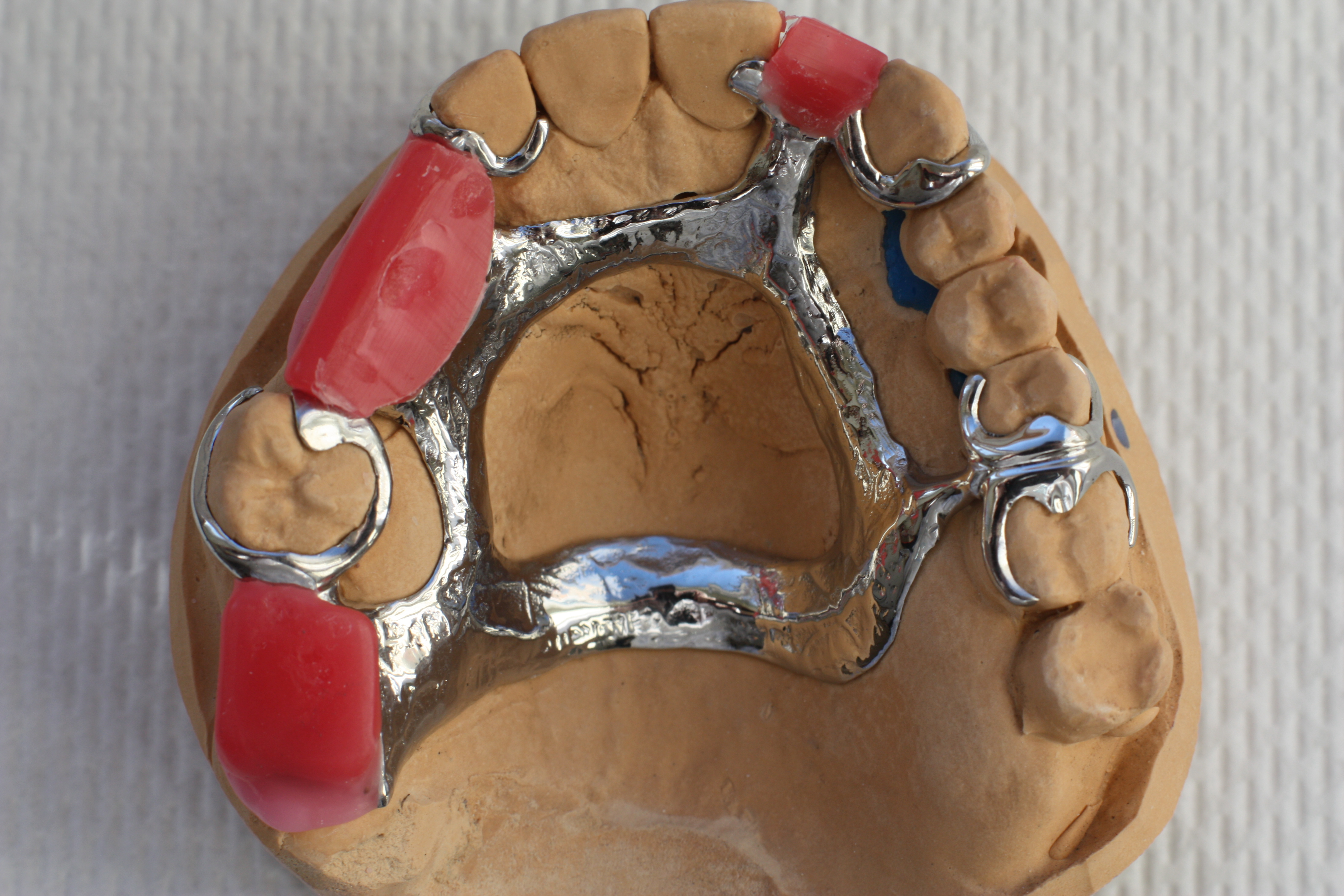
Actual maxillary cast framework on a working model. Anterior and posterior palatal elements surround an open central area; tooth-bounded saddle spaces and tooth support are visible. Pink material represents a laboratory stage, not a completed denture base. Exact bar-versus-strap dimensions, alloy composition and patient-specific prescription are not supplied by the source.
Maxillary metal framework with an anteroposterior palatal connector · Sterilgutassistentin · CC BY-SA 3.0. None; original photograph downloaded.
Palatal strap and anteroposterior bar framework designs
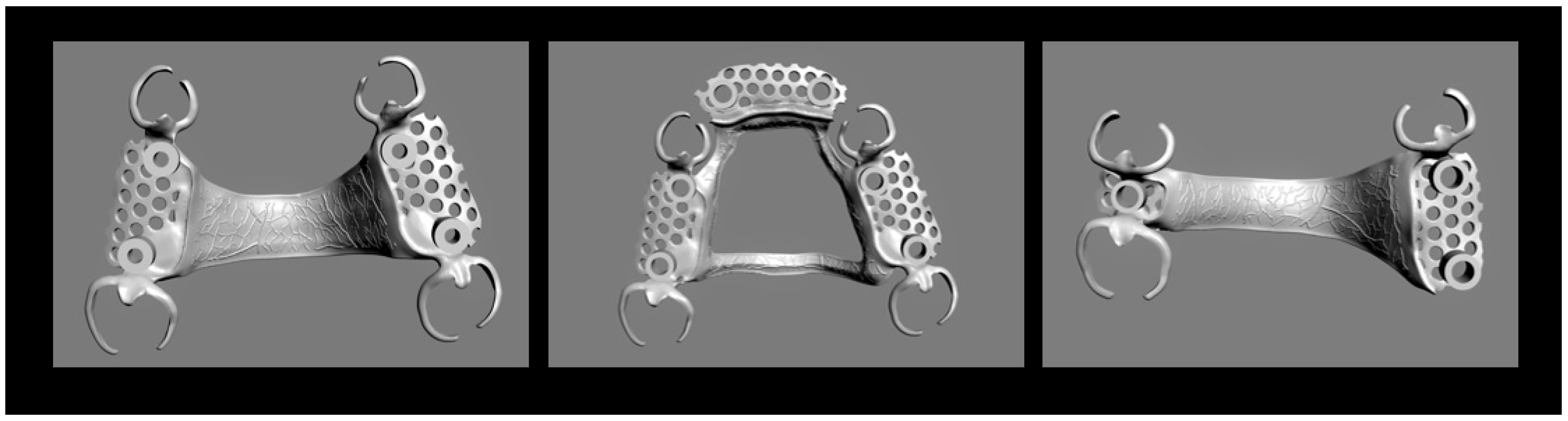
Original Figure 3 from a Co-Cr laboratory study. Left and middle use tooth-supported Kennedy III configurations; right uses a Kennedy II configuration. Source names left/right connectors palatal straps and middle anteroposterior bar. These are CAD designs without teeth or mucosa, not clinical photographs or prescriptions.
Palatal strap and anteroposterior bar framework designs · Stefan Rues; Akinori Tasaka; Isabella Fleckenstein; Shuichiro Yamashita; Peter Rammelsberg; Sophia Boehm; Franz Sebastian Schwindling · CC BY 4.0. None; high-resolution original publisher figure downloaded. Original publication.
Buccal circumferential clasp arm and clasp pattern
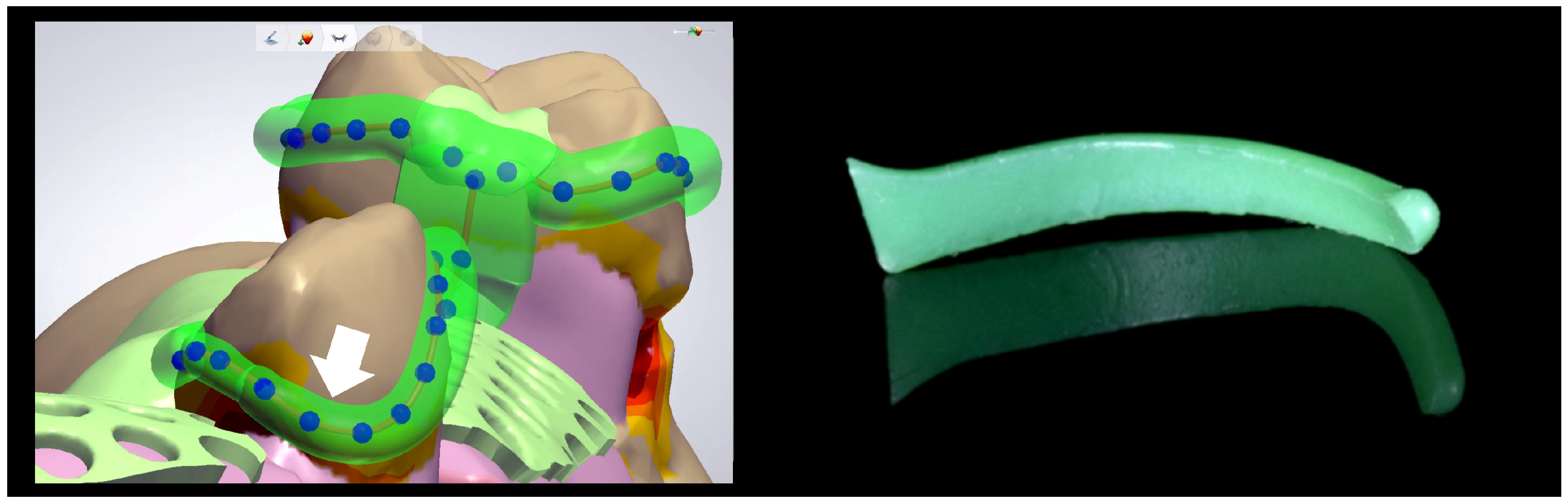
Original Figure 4. Left shows a buccal retentive clasp tip designed into a 0.25 mm undercut; right shows the preformed wax-pattern shape used as a comparison. Useful for circumferential clasp geometry. It does not separately label a reciprocal arm or demonstrate simultaneous reciprocation during insertion.
Buccal circumferential clasp arm and clasp pattern · Stefan Rues; Akinori Tasaka; Isabella Fleckenstein; Shuichiro Yamashita; Peter Rammelsberg; Sophia Boehm; Franz Sebastian Schwindling · CC BY 4.0. None; high-resolution original publisher figure downloaded. Original publication.
RPI clasp design, buccal and lingual views
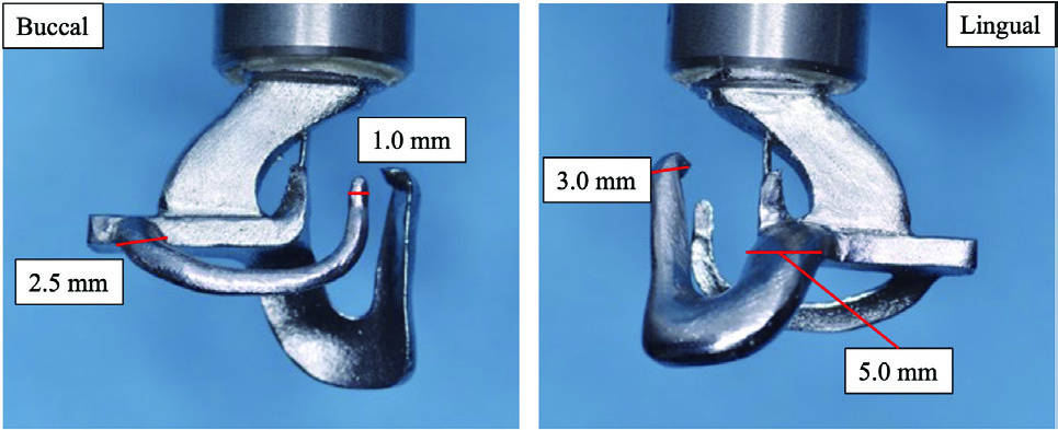
Original Figure 2: detached RPI test specimen, showing the approach arm and clasp framework from both sides. Original dimensional labels preserved. The large upper arm connects to testing machinery; dimensions describe this experiment, not general clinical requirements.
RPI clasp design, buccal and lingual views · Yuki Uekubo; Yoshimitsu Kato; Keita Tomono; Mitsuo Kato; Juro Wadachi; Shinji Takemoto; Shuichiro Yamashita · CC BY 4.0. Embedded Figure 2 JPEG extracted unchanged from original PDF; figure caption is supplied in metadata. Original publication.
RPI clasp on a prepared simulated abutment
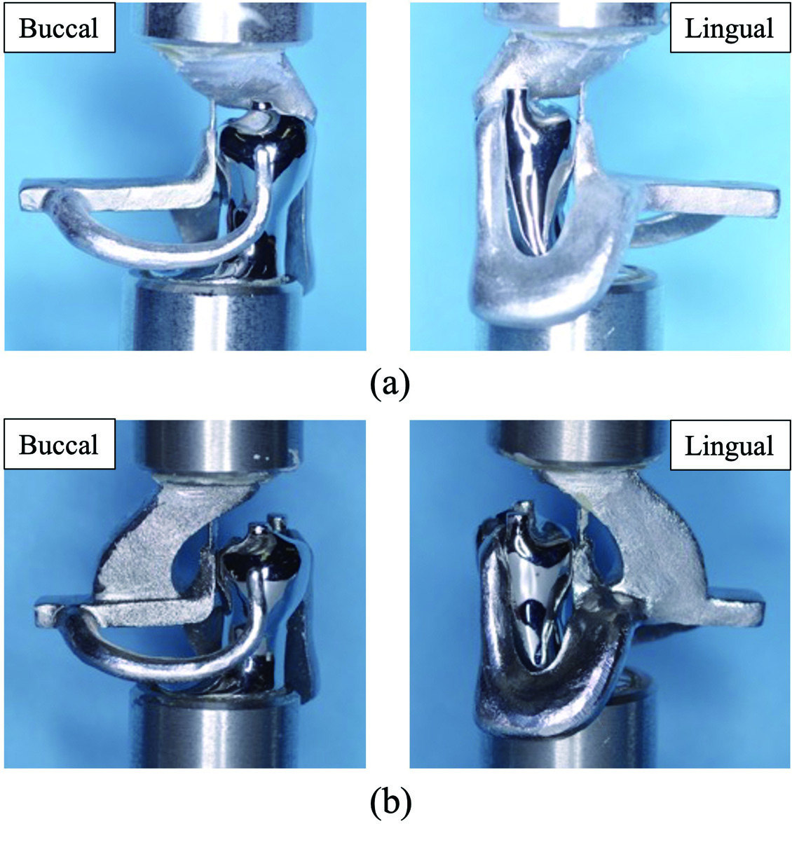
Original Figure 4: assembly seated on a simulated mandibular right second premolar. Paper describes a mesial rest, distal guide plane/proximal plate and I-bar. Panels a and b are different testing connections, not different clinical indications. Metallic teeth, upper fixtures and extensions belong to the test apparatus.
RPI clasp on a prepared simulated abutment · Yuki Uekubo; Yoshimitsu Kato; Keita Tomono; Mitsuo Kato; Juro Wadachi; Shinji Takemoto; Shuichiro Yamashita · CC BY 4.0. Embedded Figure 4 JPEG extracted unchanged from original PDF; all original labels preserved. Original publication.
Kennedy classes I–IV, original open-license schematic

Original SVG declared own work by Hans Meine, using licensed Kaligula tooth outlines. Classification concept cites Kennedy’s 1932 text; this is a modern digital drawing, not a textbook scan. Shows basic classes without modification spaces or framework designs. Roman-numeral labels retained; do not imply a connector prescription from class alone.
Kennedy classes I–IV, original open-license schematic · Hans Meine; tooth artwork based on Kaligula (CC BY-SA 3.0) · CC BY-SA 4.0. None; original SVG downloaded. Tooth outlines: Kaligula, CC BY-SA 3.0.
Jaw cysts and bone lesions
Compare cysts, tumours, fibro-osseous change and other bone findings. Read each panel key and connect the imaging pattern with the clinical assessment.
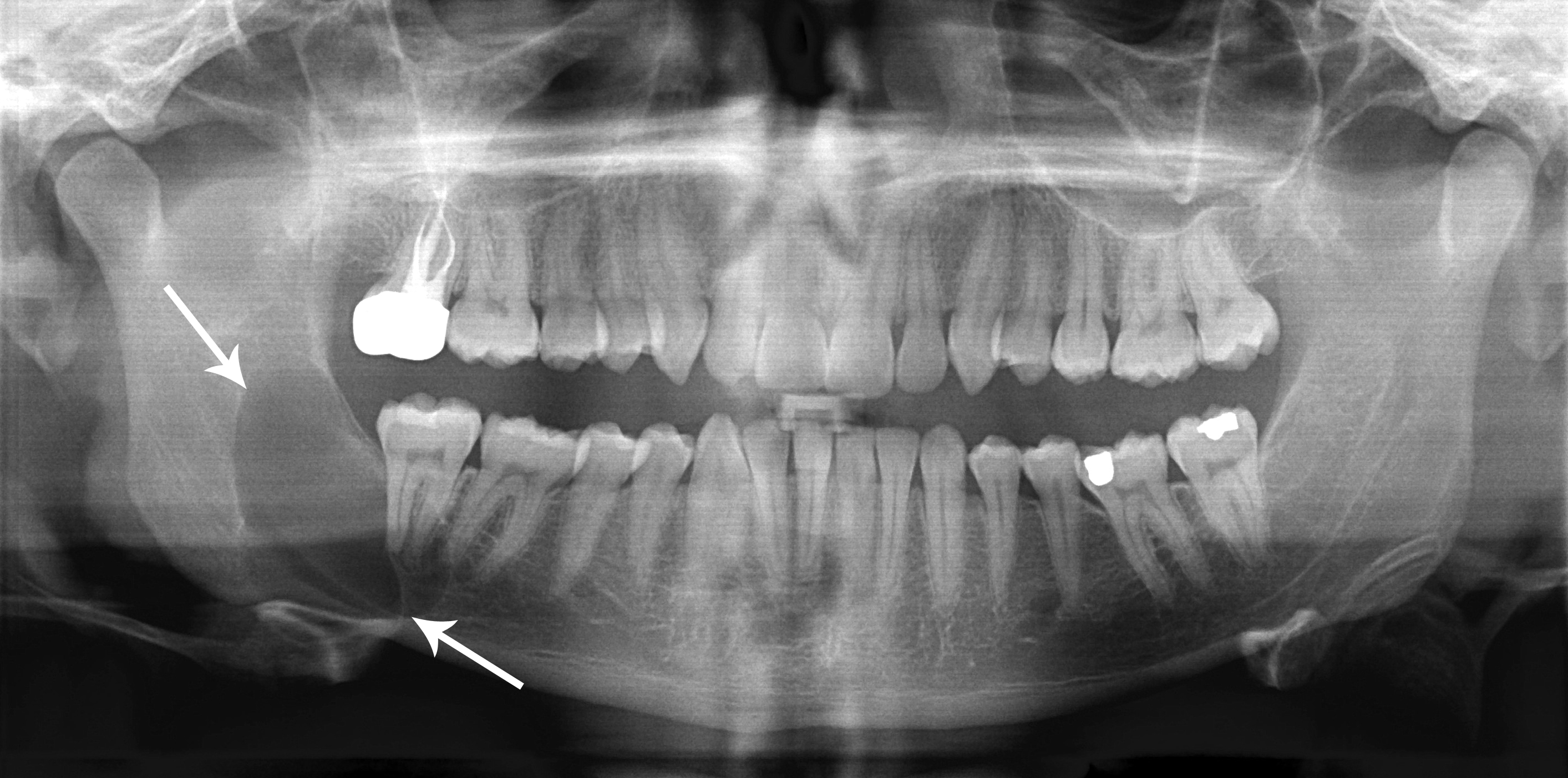
Dentigerous cyst: a pericoronal radiolucency
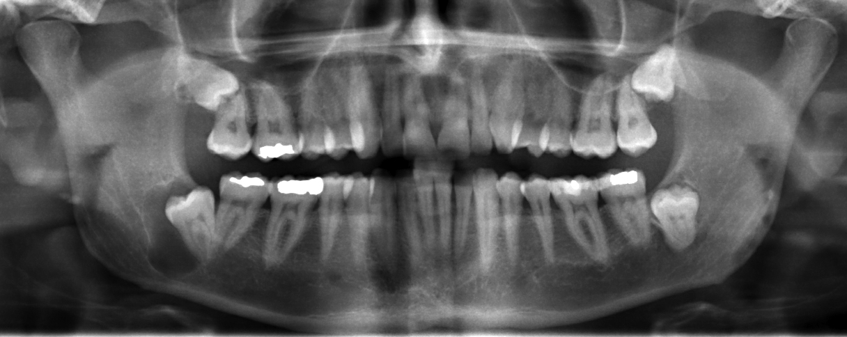
Locate the radiolucency associated with the impacted lower third molar on the left of the displayed image; the source describes a right mandibular dentigerous cyst. Assess its border and relationship to the crown, adjacent roots and mandibular canal. A pericoronal radiolucency supports a differential; imaging alone cannot establish the lining or exclude other odontogenic lesions.
JawCyst.jpg · Coronation Dental Specialty Group · CC BY 3.0. Source image reproduced without alteration; any arrows or circles are part of the original.
Which tooth relationship makes a dentigerous cyst an important consideration?
A radiolucency surrounding the crown of an unerupted tooth. An enlarged follicle and other odontogenic lesions can resemble it, so clinical, radiographic and appropriate histological findings must be correlated.
Odontogenic keratocyst: a posterior mandibular example
Use the original arrows to locate the posterior mandibular radiolucency and inspect its extent. The source diagnosis is an odontogenic keratocyst, described under the historical name “keratocystic odontogenic tumour”. Its relatively well-defined appearance does not make follow-up unnecessary. Other jaw lesions can look similar; definitive classification requires correlation with tissue findings.
Classic_keratocystic_odontogenic_tumour.jpg · Coronation Dental Specialty Group · CC BY 3.0. Source image reproduced without alteration; any arrows or circles are part of the original.
Can the relatively well-defined border distinguish this keratocyst from every other odontogenic cyst?
No. Borders and location help rank possibilities but overlap between lesions. The source diagnosis is supplied for teaching; it cannot be independently established from this panoramic image alone.
Nasopalatine duct cyst: an anterior maxillary example
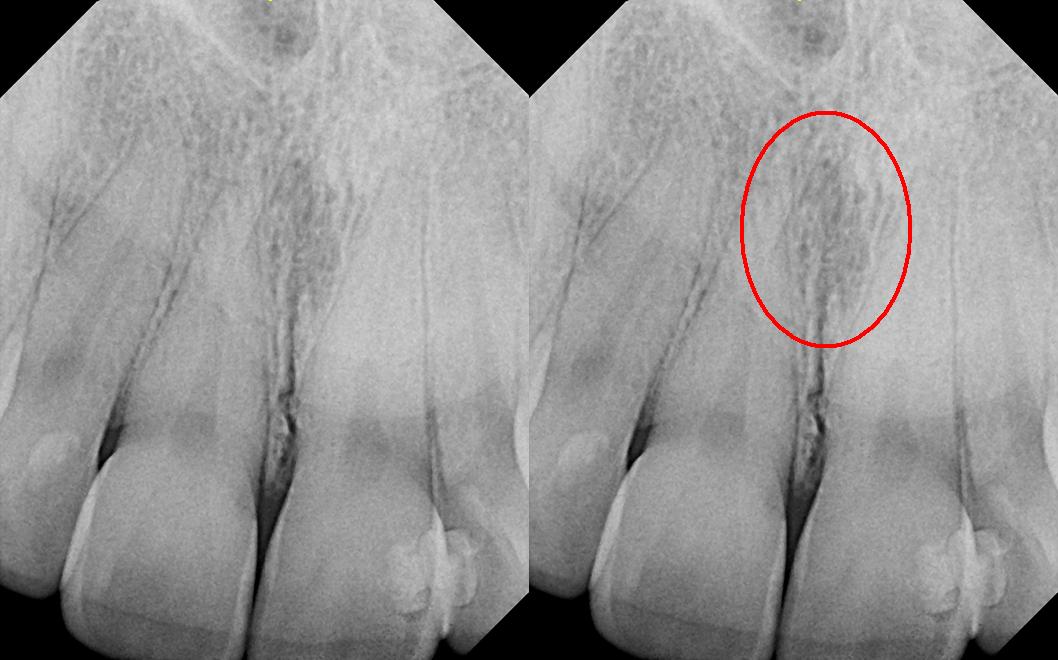
The right panel repeats the image with the source’s red circle highlighting the midline region. The source explicitly corrects its filename: this is reported as a nasopalatine duct cyst, not a nasolabial cyst. Consider the incisive canal and adjacent incisors, including pulp tests. The subtle appearance illustrates why a labelled example is not a stand-alone diagnostic rule.
Nasolabial_duct_cyst.JPG · DRosenbach · CC BY-SA 3.0. Source image reproduced without alteration; any arrows or circles are part of the original.
Why assess the adjacent incisors before treating a midline anterior maxillary radiolucency as endodontic disease?
A nasopalatine duct cyst or normal incisive-canal anatomy may overlap the incisor roots. Clinical examination, pulp tests and appropriate imaging help avoid unnecessary endodontic treatment of otherwise healthy teeth.
Ameloblastoma: expansion on axial CT
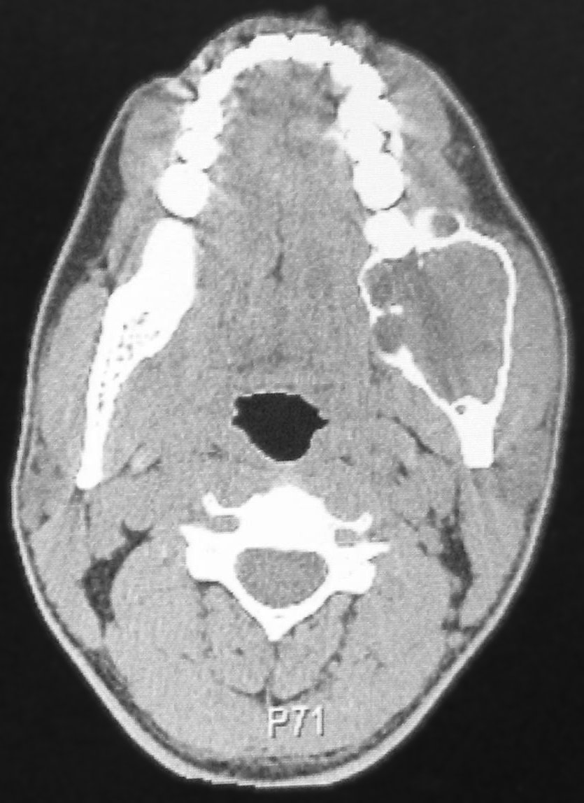
Compare the expanded posterior mandible on the right of the displayed image with the opposite side. The source reports a left mandibular ameloblastoma. Trace the remaining cortex and internal compartmental appearance. This CT example and the histology example elsewhere in the atlas come from separate teaching cases.
CT Scan of ameloblastoma.jpg · Berto1286; source-file crop and tonal adjustment by Hellerhoff · Public domain. Reproduced without alteration. Labels, arrows and circles, where present, belong to the source image.
What does this axial view show that a panoramic projection may conceal?
Buccolingual expansion and the relationship to the cortical boundaries are more directly visible. The imaging pattern informs the differential and extent assessment; tissue findings establish classification.
Stafne bone cavity: panoramic location
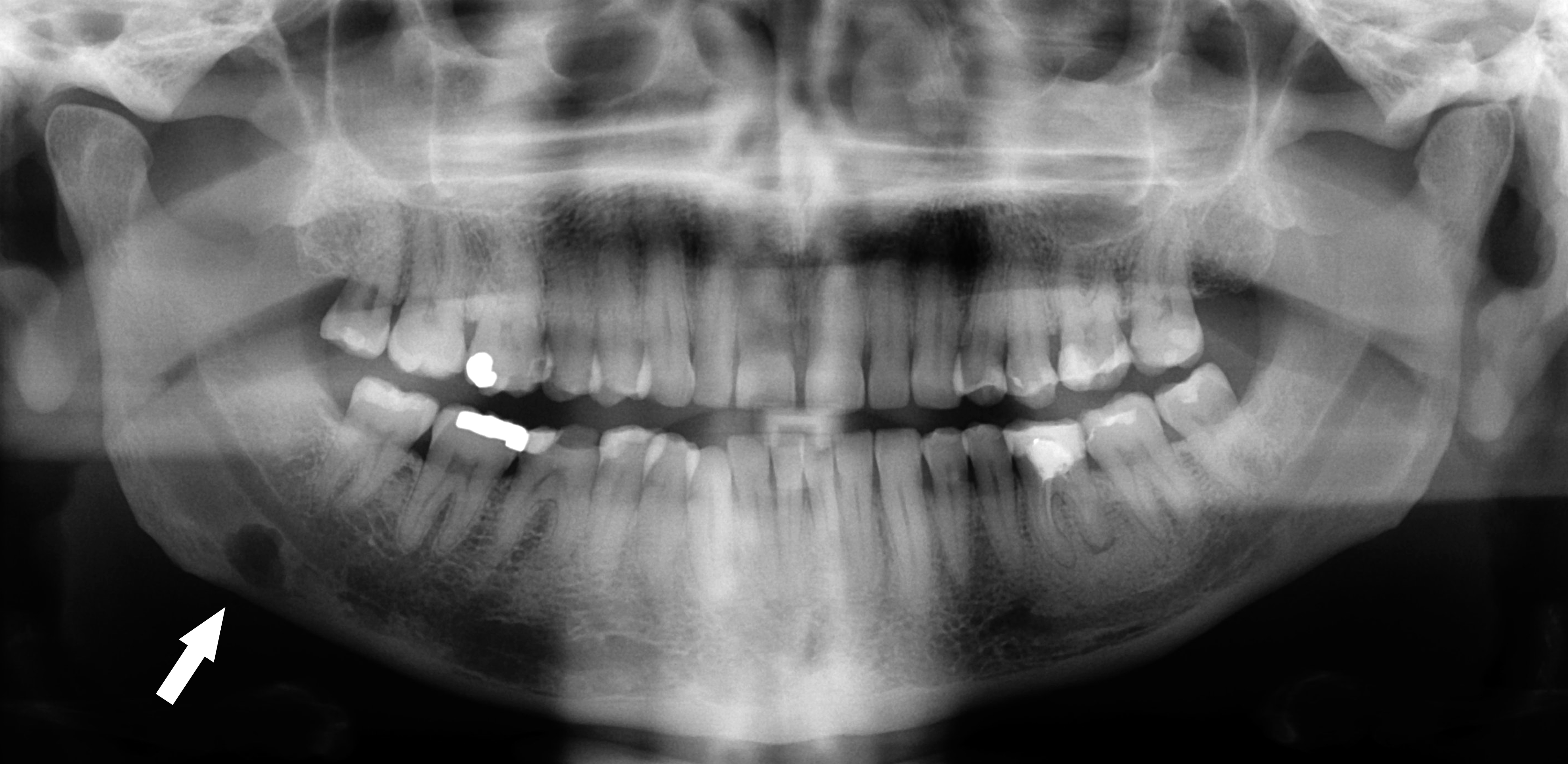
Follow the original arrow to the rounded radiolucency near the lower border of the right mandible, on the left of the displayed image. The source identifies a Stafne defect. Compare its position below the mandibular canal with the tooth-related relationships of odontogenic cysts. The axial CT shows the same source case from another plane.
Stafne defect panorex.jpg · Coronation Dental Specialty Group · CC BY 3.0. Reproduced without alteration. Labels, arrows and circles, where present, belong to the source image.
Which anatomical relationship is particularly helpful in this example?
Its location below the mandibular canal near the posterior lower border. Use the full pattern and clinical context; that relationship alone is not a universal rule for every radiolucency.
Stafne bone cavity: the lingual depression on CT
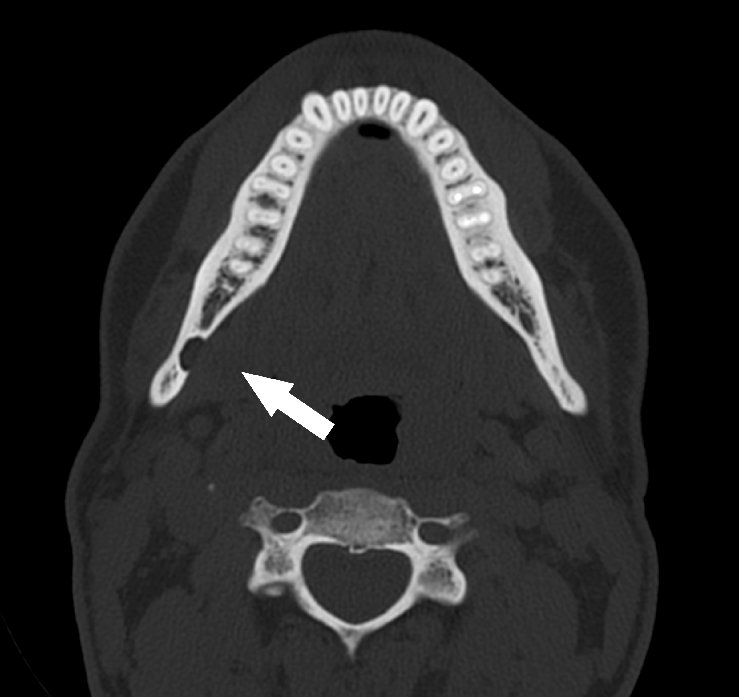
The original arrow marks a concavity in the lingual mandibular cortex. Compare it with the panoramic example of the same source case. This helps explain why a two-dimensional radiolucency can represent a bony depression rather than an epithelial-lined odontogenic cyst. Further imaging in a real case needs an individual clinical indication.
Stafne defect CT axial.jpg · Coronation Dental Specialty Group · CC BY 3.0. Reproduced without alteration. Labels, arrows and circles, where present, belong to the source image.
Why should a Stafne bone cavity not automatically be called a true odontogenic cyst?
It represents a mandibular bony depression rather than an epithelial-lined tooth-derived cyst. Classification depends on the complete assessment.
Periapical sclerosis: compare four patterns
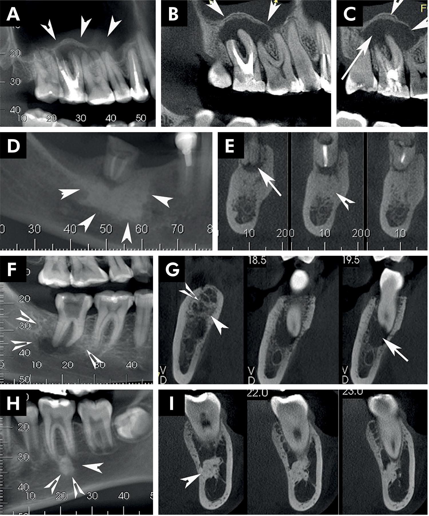
Compare the source diagnoses below. Tooth findings and lesion distribution help interpret the opacity.
Panel key
- A–C
- Reactive bone associated with inflammatory change.
- D–E
- Condensing osteitis.
- F–G
- Chronic osteomyelitis.
- H–I
- Idiopathic osteosclerosis.
Periapical radiopaque-hyperdense jaw lesions 1.jpg · Brunno Santos Freitas Silva, Mike Reis Bueno, Fernanda P. Yamamoto-Silva, Ricardo Santiago Gomez, Ove Andreas Peters and Carlos Estrela · CC BY 4.0. Reproduced without alteration. Labels, arrows and circles, where present, belong to the source image. Original publication.
Does periapical opacity alone establish an endodontic diagnosis?
No. Correlate it with tooth assessment and the broader pattern.
Cemento-osseous dysplasia: localised and florid examples
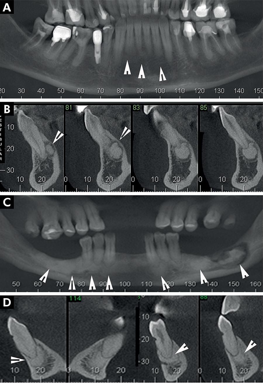
Compare the distribution and separation from roots in the source examples.
Panel key
- A–B
- Periapical cemento-osseous dysplasia.
- C–D
- Florid cemento-osseous dysplasia; the source also describes sequestration in C.
Periapical radiopaque-hyperdense jaw lesions 2.jpg · Brunno Santos Freitas Silva, Mike Reis Bueno, Fernanda P. Yamamoto-Silva, Ricardo Santiago Gomez, Ove Andreas Peters and Carlos Estrela · CC BY 4.0. Reproduced without alteration. Labels, arrows and circles, where present, belong to the source image. Original publication.
Why assess the teeth before attributing these findings to pulp disease?
The imaging distribution may have a non-endodontic explanation.
Fibrous dysplasia, osteoma and cementoblastoma
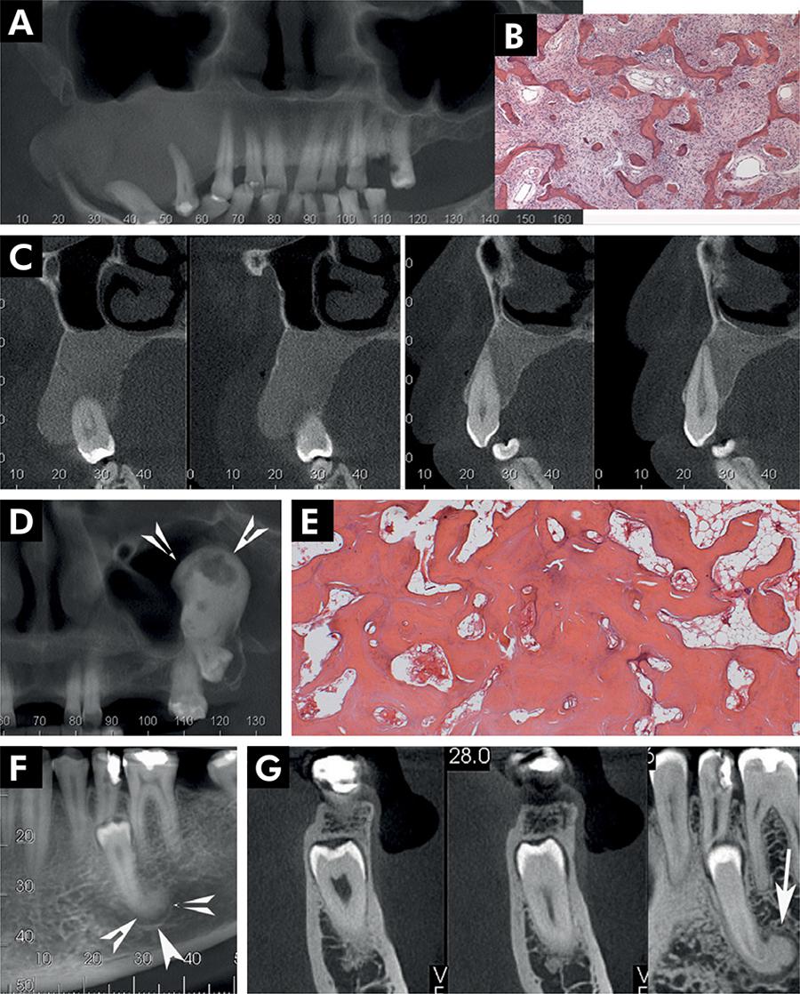
Compare the margins and root relationships of these source cases.
Panel key
- A–C
- Fibrous dysplasia.
- D–E
- Central osteoma.
- F–G
- Cementoblastoma.
Periapical radiopaque-hyperdense jaw lesions 3.jpg · Brunno Santos Freitas Silva, Mike Reis Bueno, Fernanda P. Yamamoto-Silva, Ricardo Santiago Gomez, Ove Andreas Peters and Carlos Estrela · CC BY 4.0. Reproduced without alteration. Labels, arrows and circles, where present, belong to the source image. Original publication.
Which relationship deserves attention in the cementoblastoma panels?
The lesion’s attachment to the root.
Odontomas and other calcified jaw lesions
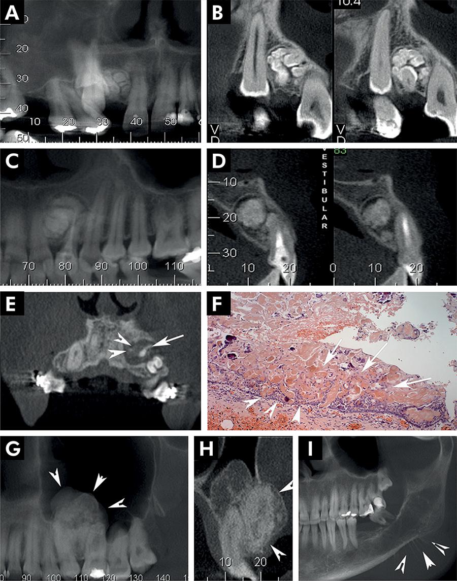
Use the panel key to compare the source diagnoses. The historical label CCOT corresponds here to calcifying odontogenic cyst.
Panel key
- A–B
- Compound odontoma.
- C–D
- Complex odontoma.
- E–F
- Calcifying odontogenic cyst (source label: CCOT).
- G–H
- Adenomatoid odontogenic tumour.
- I
- Source example of osteosarcoma.
Periapical radiopaque-hyperdense jaw lesions 4.jpg · Brunno Santos Freitas Silva, Mike Reis Bueno, Fernanda P. Yamamoto-Silva, Ricardo Santiago Gomez, Ove Andreas Peters and Carlos Estrela · CC BY 4.0. Reproduced without alteration. Labels, arrows and circles, where present, belong to the source image. Original publication.
Does calcification establish benignity?
No. Compare the entire lesion and clinical findings.
Oral medicine and salivary lesions
Compare ulcers, tongue changes, white lesions, infection, salivary findings and cancer. Describe the visible features before reading the source diagnosis.
Oral lichen planus: reticular white striae
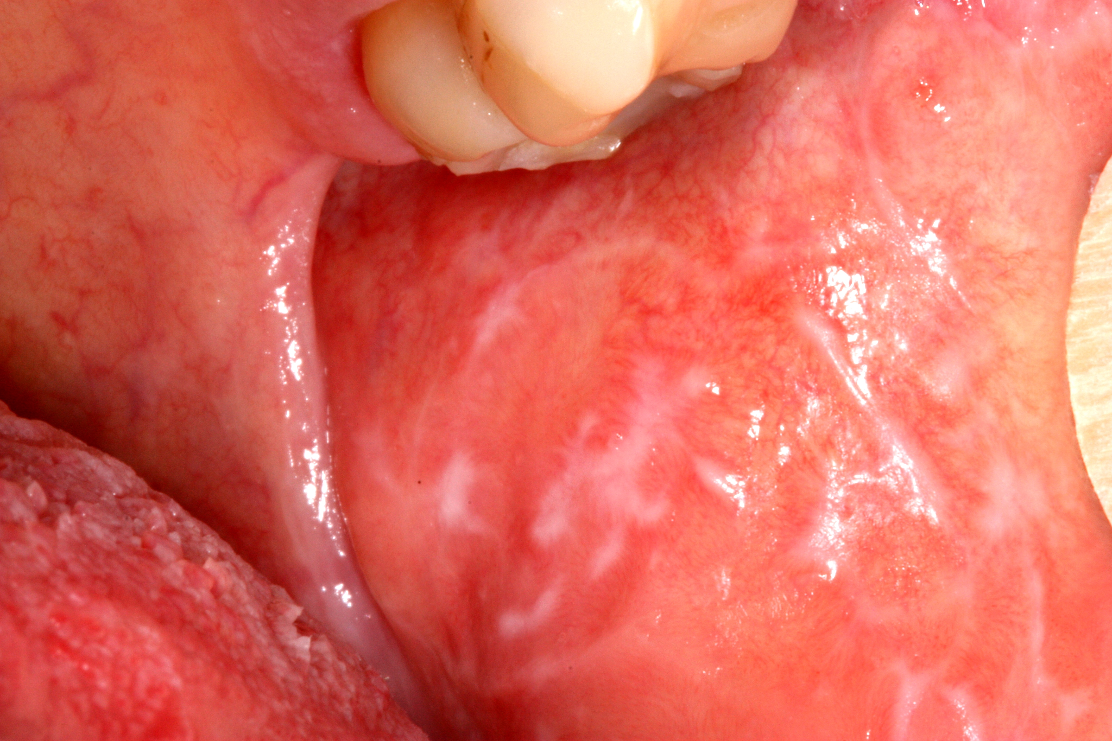
Follow the fine, intersecting white lines across the buccal mucosa. The source identifies this as non-erosive oral lichen planus. In practice, examine the distribution elsewhere in the mouth and consider lichenoid reactions; a photograph cannot establish the full clinical or histological diagnosis.
Lichen_planus.jpg · Ian Furst · CC BY-SA 4.0. Source image reproduced without alteration; any arrows or circles are part of the original.
Which visible feature gives this lesion a reticular pattern?
The interlacing white striae form a lace-like network. Describe that pattern before interpreting it, then correlate with distribution, history and appropriate clinical assessment.
Oral lichen planus: a mixed red and white appearance
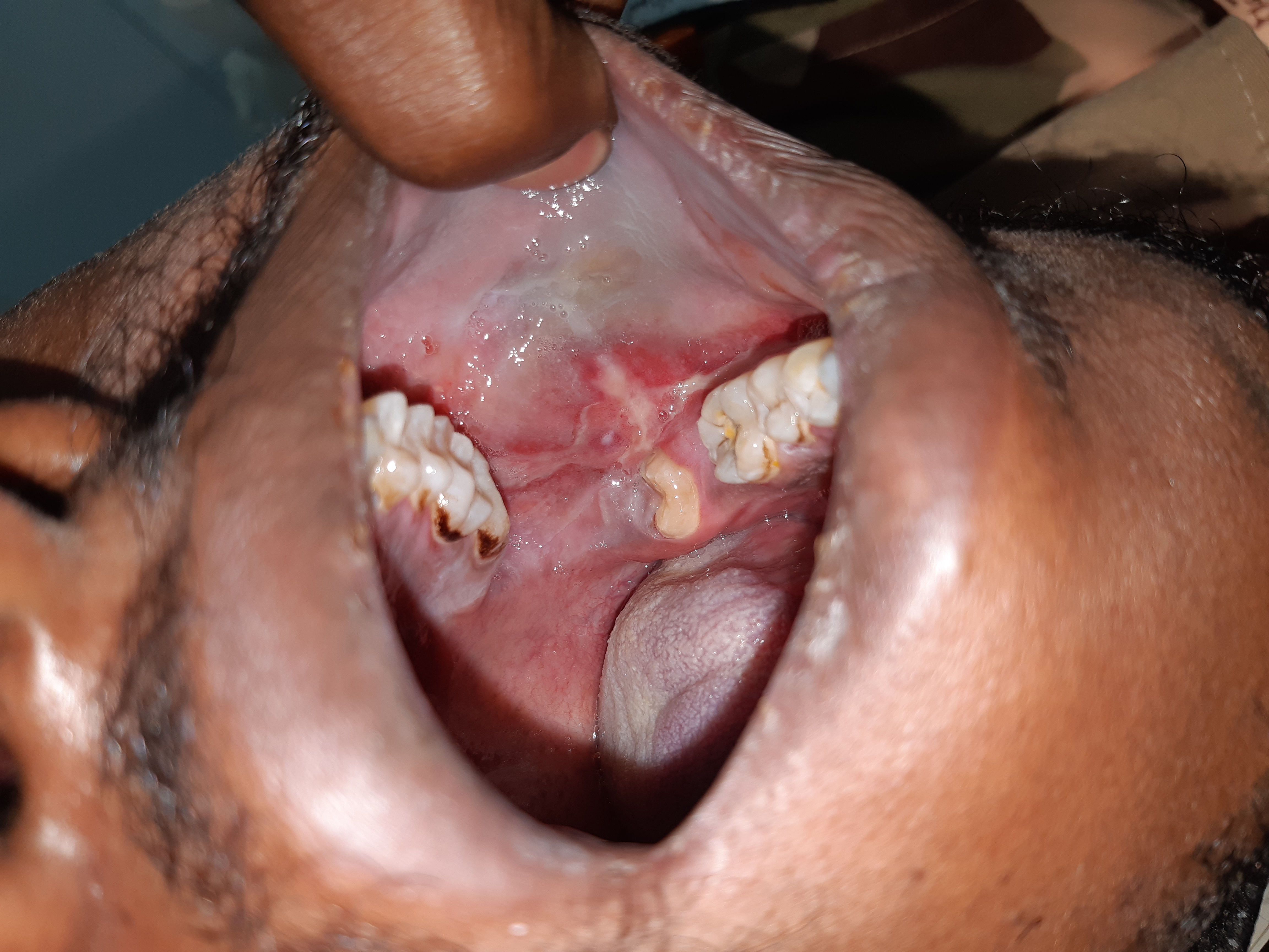
Compare the white striae and thicker white areas with the adjacent erythematous mucosa. The source labels this case oral lichen planus. A red or ulcerated area needs assessment in its own right: symptoms, change, induration and a persistent focal abnormality matter, even when a background lichenoid pattern is familiar.
Lichen_planus-intra_oral_lesion.jpg · Syed Wali Peeran · CC BY-SA 4.0. Source image reproduced without alteration; any arrows or circles are part of the original.
Does recognising a lichenoid pattern explain every red area in the photograph?
No. Describe and assess each significant area. Lichenoid disease, trauma, infection and dysplasia can overlap clinically; a persistent or changing focal lesion may need specialist assessment and biopsy.
Leukoplakia: a focal white plaque
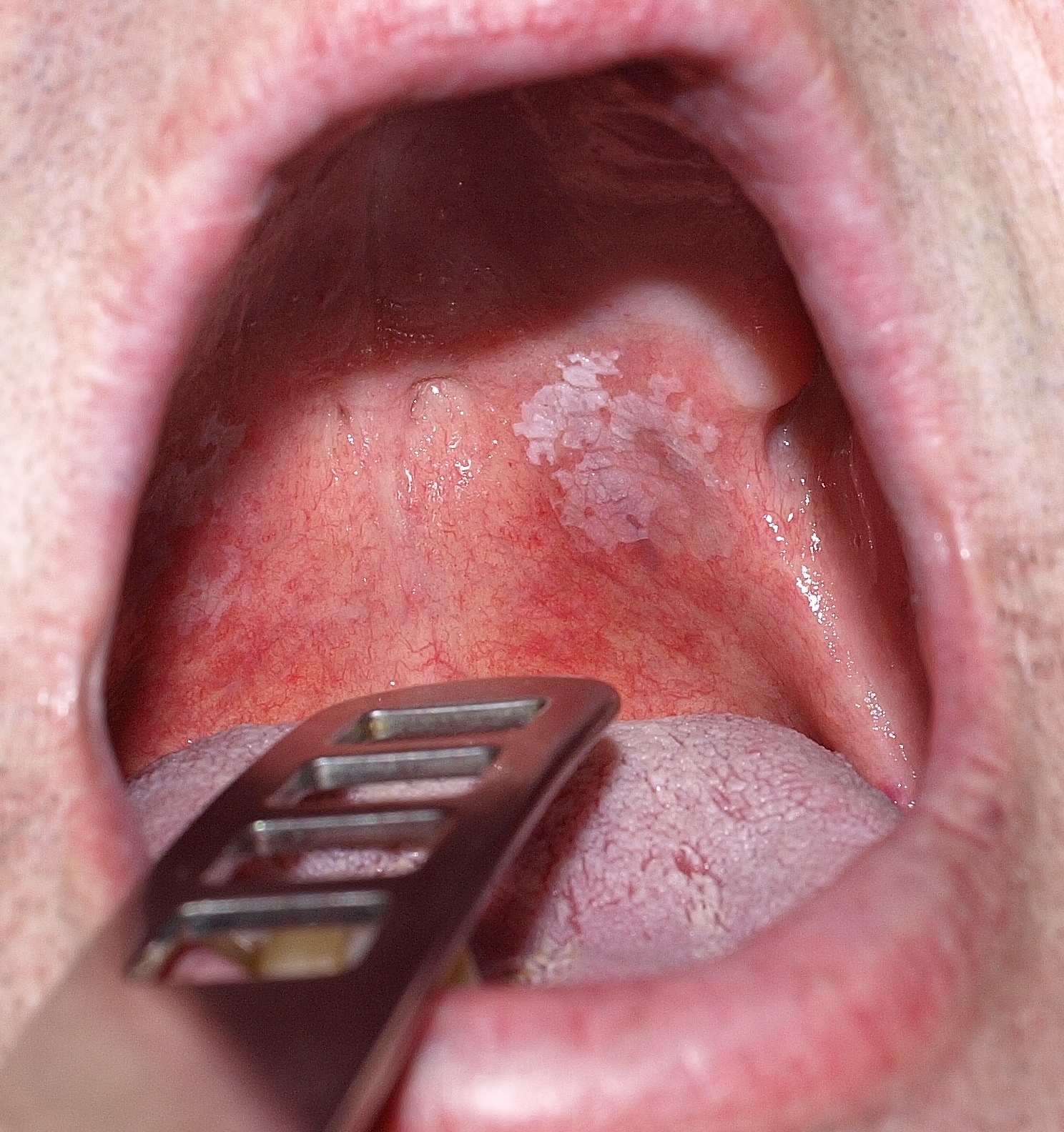
Describe the plaque’s site, outline, surface and surrounding mucosa before proposing a diagnosis. The source calls this lesion leukoplakia and reports that malignancy was excluded histologically in that case. That result cannot be inferred from its appearance or applied to another patient; white colour alone does not establish benignity.
Orale_Leukoplakie.jpg · Klaus D. Peter, Gummersbach, Germany · CC BY 3.0 DE. Source image reproduced without alteration; any arrows or circles are part of the original.
Can this photograph tell you whether the plaque contains epithelial dysplasia?
No. Dysplasia is a histological assessment. Clinical features guide the differential, urgency and sampling, but the photograph alone cannot grade or exclude it.
Oral candidosis: pseudomembranous plaques
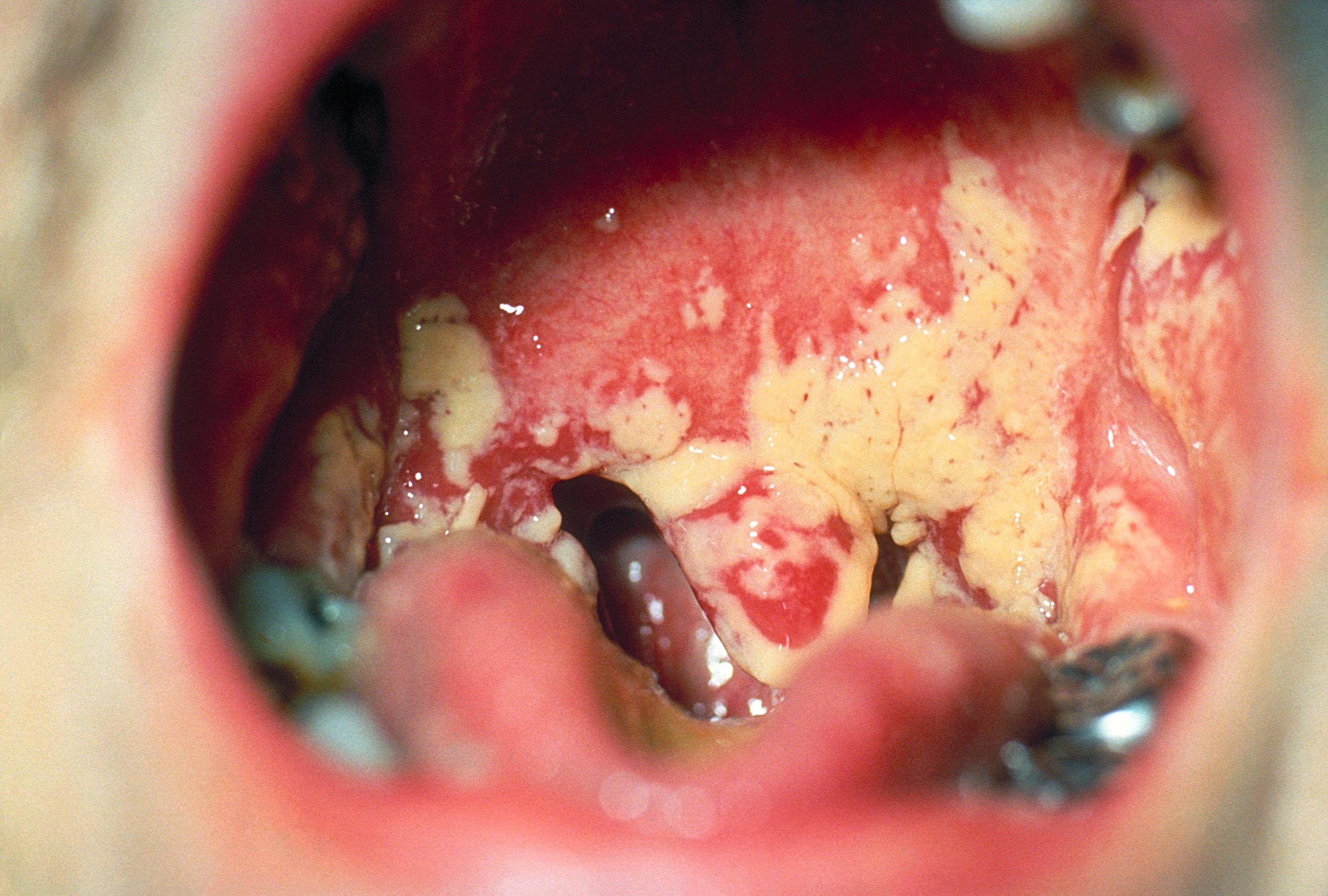
The CDC source identifies oral candidosis. Note the cream-coloured plaques over erythematous mucosa. Pseudomembranous candidosis often has removable deposits, but a static photograph cannot demonstrate that behaviour. Correlate with examination and factors such as medicines, denture use, dry mouth and immunosuppression. The legacy filename includes “Aphthae”; this is not an aphthous-ulcer example.
Oral_thrush_Aphthae_Candida_albicans._PHIL_1217_lores.jpg · Centers for Disease Control and Prevention (CDC), PHIL 1217 · Public domain (US federal government). Source image reproduced without alteration; any arrows or circles are part of the original.
What bedside observation helps distinguish pseudomembranous candidosis from a fixed white plaque?
Whether the deposit can be gently removed, often exposing erythematous mucosa. Interpret this with the history and examination; not every white lesion is candidosis.
Aphthous ulcer: labial mucosa
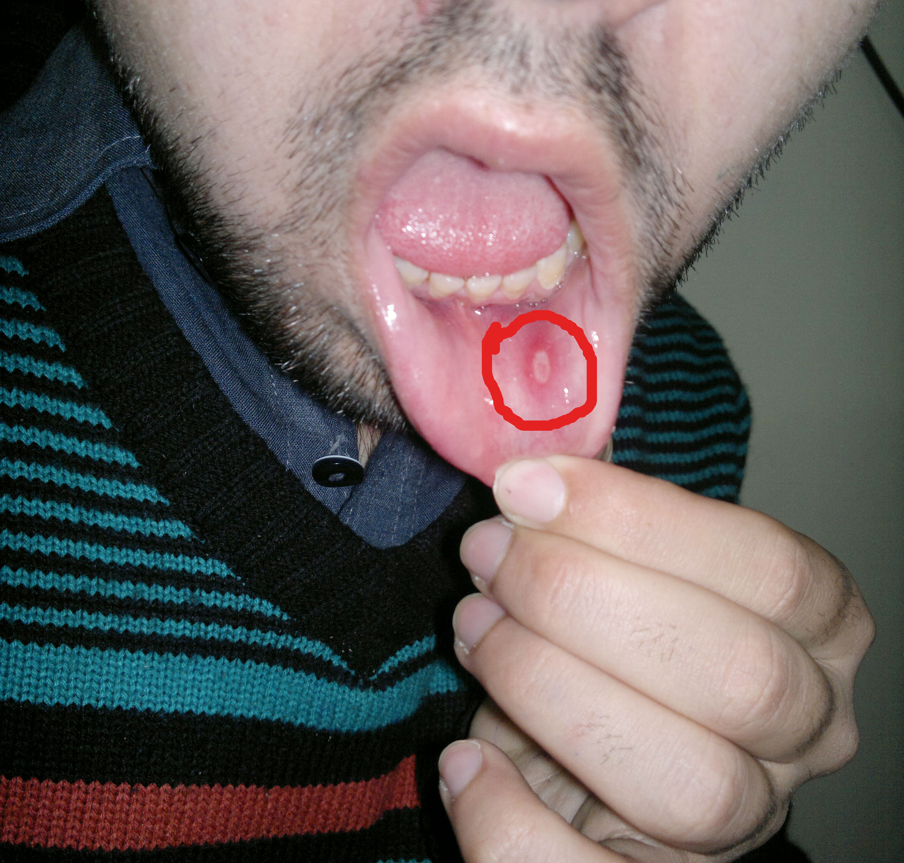
Locate the oval ulcer within the original red circle. Its pale floor and erythematous surround illustrate an aphthous appearance on labial mucosa. The history of recurrence, duration, healing and symptoms elsewhere helps distinguish recurrent aphthous stomatitis from other causes of ulceration.
Aphthous stomatitis on the labial mucosa.jpg · Farhan 9909 · CC BY-SA 4.0. Reproduced without alteration. Labels, arrows and circles, where present, belong to the source image.
What information would make an aphthous explanation more convincing?
A compatible history of recurrent, self-healing episodes and distribution, interpreted with examination. A persistent unexplained ulcer still needs assessment even if it resembles an earlier aphthous lesion.
Geographic tongue: map-like depapillation
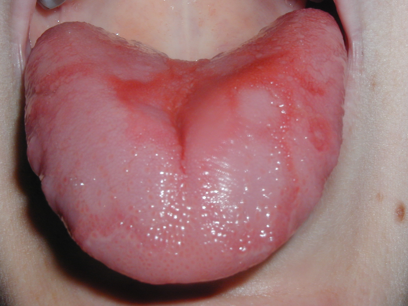
Follow the irregular red areas and their pale curving borders. The source identifies geographic tongue. The changing distribution over time is clinically useful: a single photograph shows a pattern but cannot demonstrate migration. Compare this broad map-like appearance with the more localised midline change in the median rhomboid glossitis example.
Geographic Tongue.jpg · Jaksmata · CC BY-SA 3.0. Reproduced without alteration. Labels, arrows and circles, where present, belong to the source image.
Which feature needs a history or serial photographs rather than one static image?
Migration: the shape and position can change over time. Ask about the course and inspect the whole tongue rather than inferring change from one photograph.
Lower-lip squamous cell carcinoma
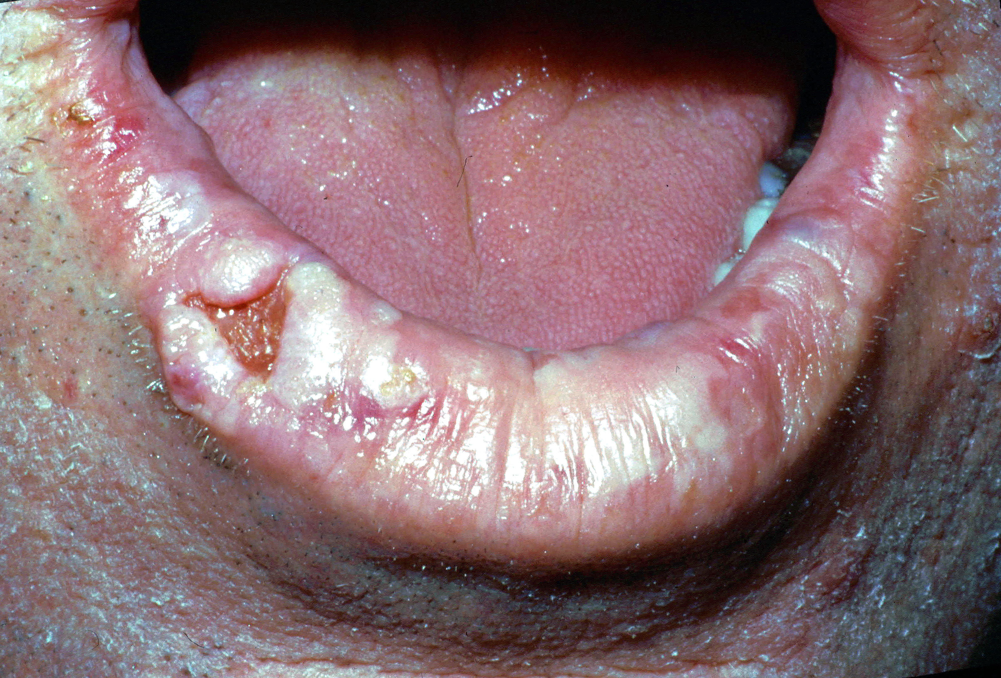
The source diagnosis is squamous cell carcinoma of the right lower lip. Describe the irregular ulcerated area, raised tissue and surrounding lip change. A clinical assessment also needs palpation, duration, progression, nodes and relevant exposures. A photograph cannot establish tumour depth or stage.
Lower lip cancer.jpg · Coronation Dental Specialty Group · CC BY-SA 4.0. Reproduced without alteration. Labels, arrows and circles, where present, belong to the source image.
Which important examination findings cannot be judged reliably from this photograph?
Induration, fixation, depth and regional lymph-node findings require clinical assessment. Tissue diagnosis and appropriate staging investigations add information that a surface photograph cannot supply.
Angular cheilitis: commissural inflammation
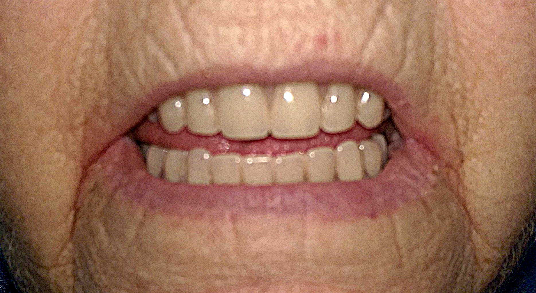
Inspect the mouth corners for redness and fissuring. The source records angular cheilitis in a person with full dentures and deep commissural folds. Assess local moisture, denture factors and relevant medical or nutritional contributors. The visible pattern does not identify Candida or another organism by itself.
Angular cheilitis.jpg · Matthew Ferguson 57 · CC BY-SA 3.0. Reproduced without alteration. Labels, arrows and circles, where present, belong to the source image.
Does the appearance alone establish that Candida is the cause?
No. Angular cheilitis can have several contributing factors. The history, examination and response to appropriate measures guide whether further investigation is needed.
Median rhomboid glossitis: central papillary change
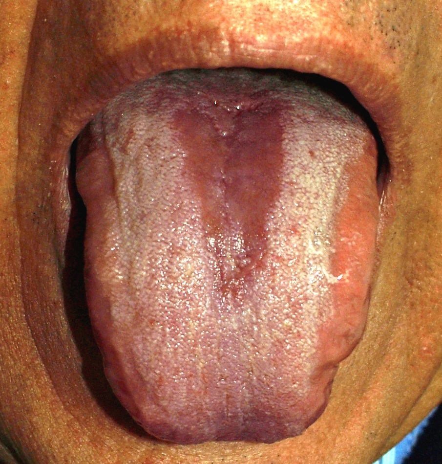
The source identifies median rhomboid glossitis. Locate the relatively smooth red midline area and compare it with the surrounding papillary surface. Describe the site and shape before interpreting the cause. A photograph does not demonstrate fungal organisms, and treatment decisions depend on symptoms and the wider assessment.
Glossitis.jpg · Klaus D. Peter, Wiehl, Germany · CC BY 3.0 DE. Reproduced without alteration. Labels, arrows and circles, where present, belong to the source image.
How does its distribution differ from the geographic-tongue example?
This example has a more localised central area. Geographic tongue shows an irregular map-like pattern whose distribution may change over time.
Submandibular duct stone at the opening
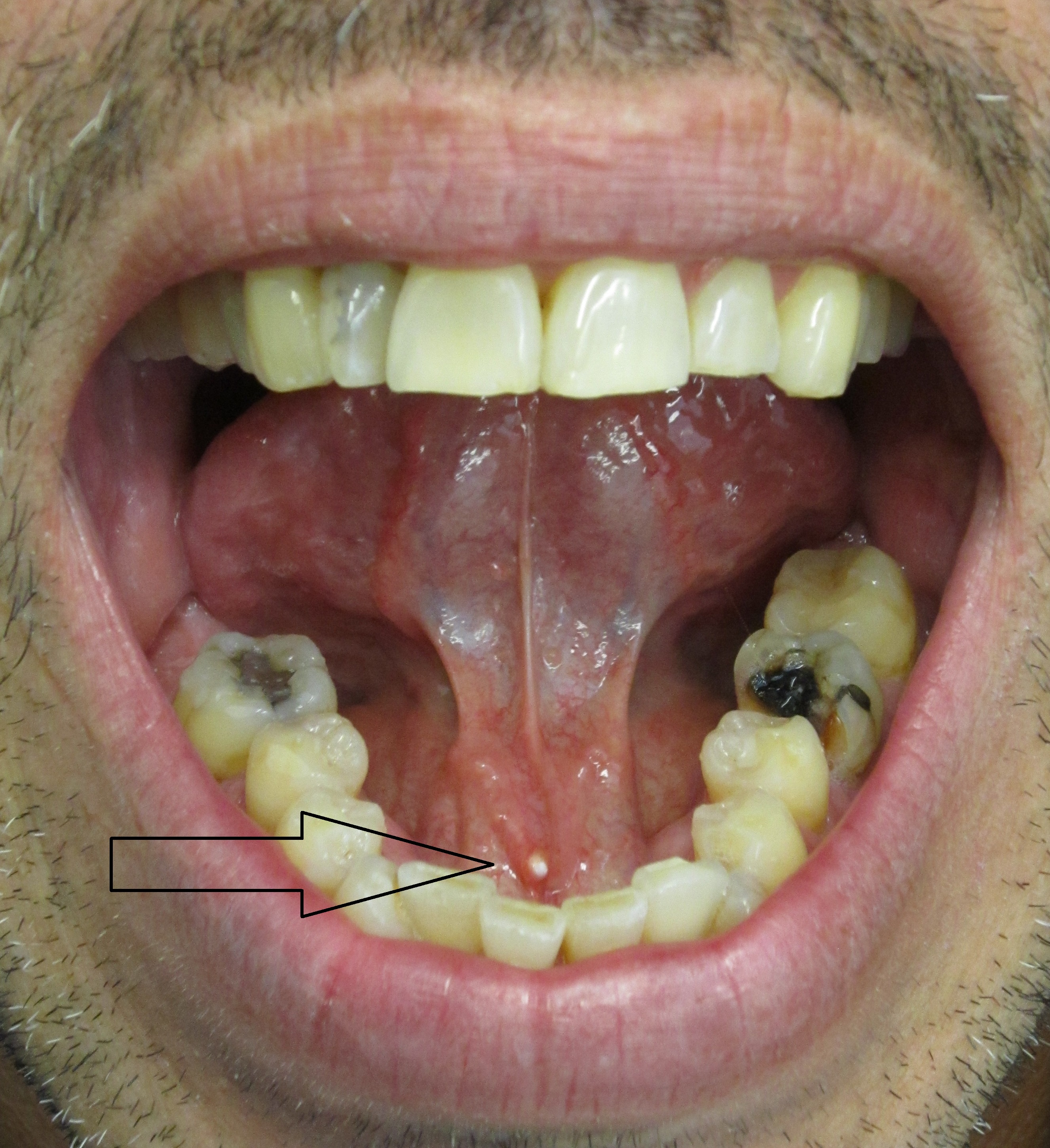
Use the original arrow to locate the pale stone at the submandibular duct opening. Relate the position to the lingual frenulum. Ask about meal-related swelling and assess the gland, duct and saliva. A visible distal calculus does not exclude another obstruction or associated infection elsewhere in the system.
Salivary stone in submandibular salivary duct.jpg · James Heilman, MD · CC BY-SA 3.0. Reproduced without alteration. Labels, arrows and circles, where present, belong to the source image.
Why can gland swelling become more noticeable around meals?
Salivary stimulation increases flow against an obstruction, which can produce swelling and pain. Correlate the timing with examination rather than diagnosing every meal-related swelling as a stone.
Mandibular trauma
Trace the entire mandible, compare single and multiple fractures and connect the image with clinical occlusion and wider trauma assessment.
Mandibular body fracture: follow the cortex
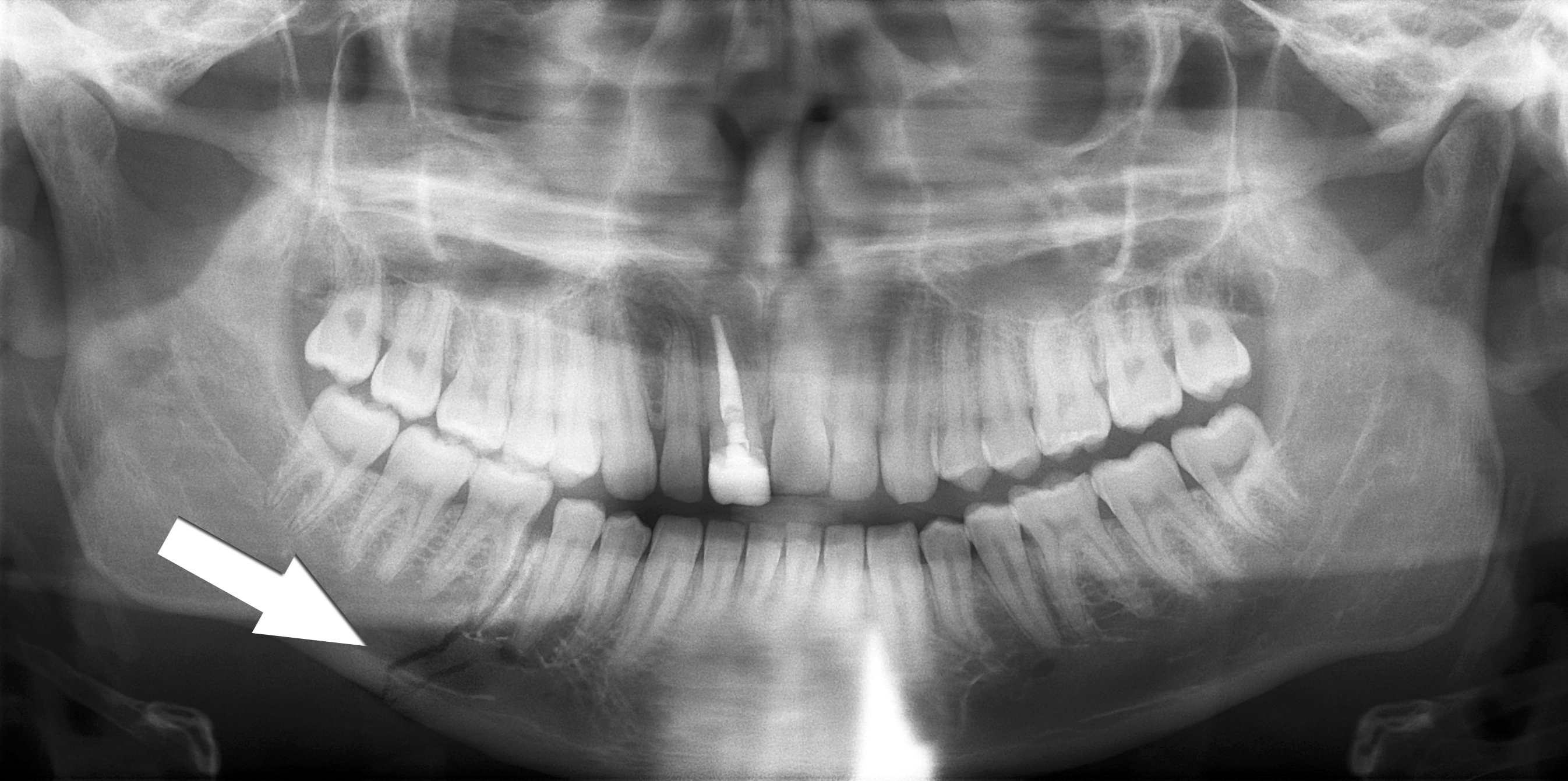
Trace the lower mandibular border through the fracture marked by the source arrow. Inspect the teeth and the remaining mandible as well as the marked site. The source describes a right body fracture. Clinical occlusion, soft tissues, sensation and the mechanism of injury remain part of the trauma assessment.
Simple mandible fracture.jpg · Coronation Dental Specialty Group · CC BY 3.0. Reproduced without alteration. Labels, arrows and circles, where present, belong to the source image.
Why should the search continue after finding the marked fracture?
Another fracture or associated injury may be present. Review the whole image and the patient’s clinical findings rather than stopping at the first abnormality.
Multiple mandibular fractures: inspect every region
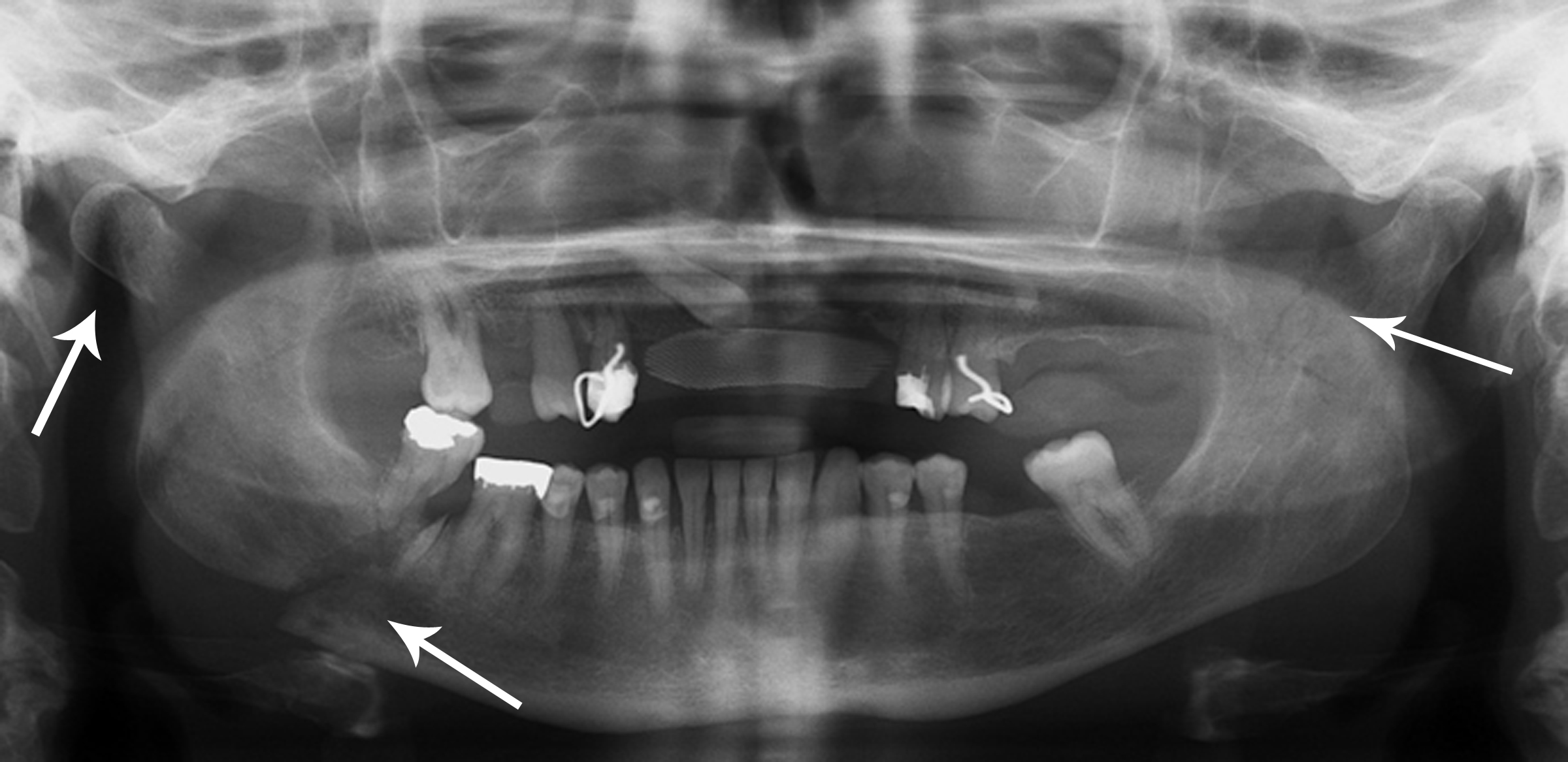
The source records right condylar and body fractures and a left coronoid fracture. Use the original arrows to orient the search, then trace each border systematically. A panoramic projection has overlap and positional limitations; a single teaching image cannot establish the complete injury pattern or its management.
Multiple mandible fractures.jpg · Coronation Dental Specialty Group · CC BY 3.0. Reproduced without alteration. Labels, arrows and circles, where present, belong to the source image.
Which clinical information is needed alongside the fracture pattern?
Airway and wider trauma assessment, occlusion, mouth opening, dental and soft-tissue injury, sensory findings and relevant patient factors, with additional investigations chosen for the clinical question.
Histopathology examples
Orient yourself in real tissue sections. These specimens complement the imaging examples and are separate teaching cases unless explicitly stated otherwise.
Ameloblastoma: epithelial islands on histology
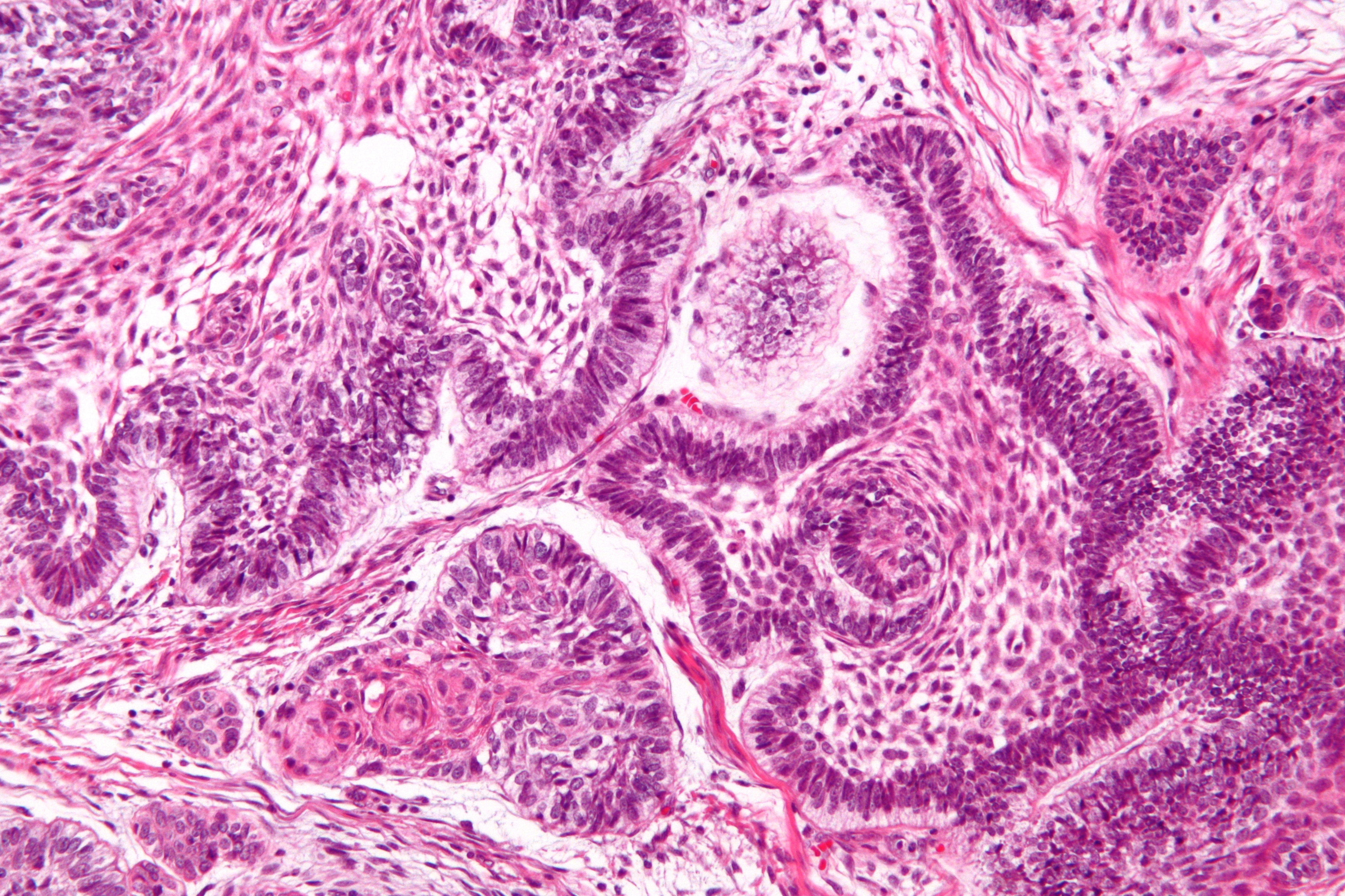
Locate the epithelial islands within the connective-tissue stroma. The source identifies peripheral palisading, reverse nuclear polarisation and central stellate-reticulum-like cells. This is a separate specimen from the CT teaching case. A complete diagnosis considers the sampled architecture and the clinical and radiographic findings.
Ameloblastoma - high mag.jpg · Nephron · CC BY-SA 3.0. Reproduced without alteration. Labels, arrows and circles, where present, belong to the source image.
What does reverse nuclear polarisation refer to in this teaching example?
The nuclei of peripheral cells lie away from the basement-membrane side. It is interpreted with the wider architecture rather than treated as an isolated diagnostic rule.
Odontoma: dental hard-tissue architecture
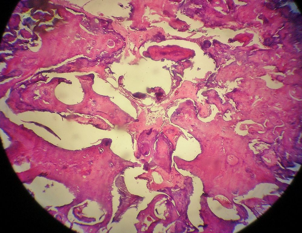
The source identifies an odontoma. Inspect how the dental tissues are organised and compare this tissue view with the atlas’s radiographic odontoma panels, which show different teaching cases. Imaging describes the mineralised pattern and tooth relationships; histology assesses the tissue architecture.
Odontoma.jpg · JXtra · CC BY-SA 3.0. Reproduced without alteration. Labels, arrows and circles, where present, belong to the source image.
Why keep the radiographic and histological descriptions distinct?
They describe different aspects of the lesion. A radiopaque pattern is not itself a microscopic diagnosis, and the specimen must be interpreted with the case information.
Mucocele: low-power tissue appearance
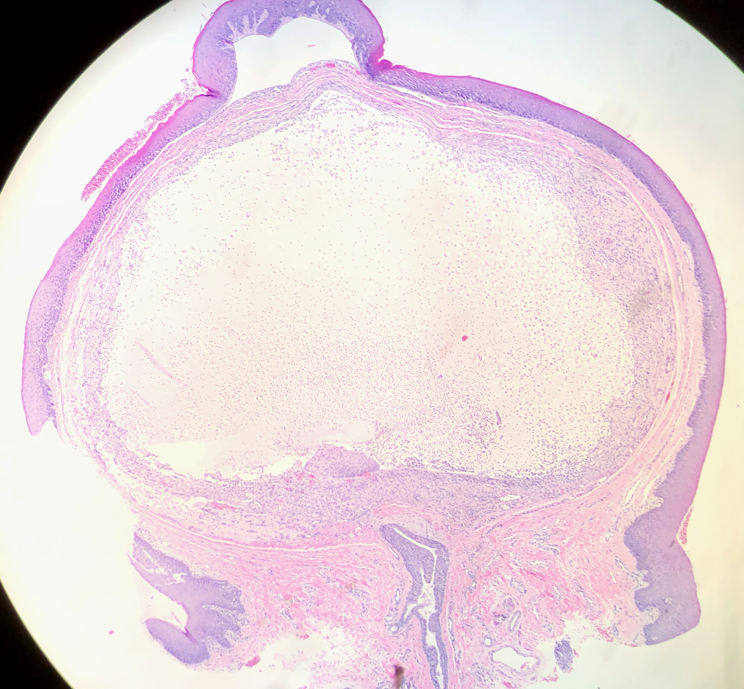
The source identifies a lower-lip mucocele. Orient yourself at the surface epithelium, then find the large pale mucin-rich area beneath it and the surrounding tissue reaction. Distinguishing mucous extravasation from a duct-lined retention lesion requires attention to the complete specimen and report.
Mucocele of Lower Lip (49425670122).jpg · Ed Uthman · CC BY 2.0. Reproduced without alteration. Labels, arrows and circles, where present, belong to the source image.
Which tissue relationship is important when interpreting a mucocele specimen?
The relationship of mucin, the surrounding reaction and any duct or epithelial lining. A cavity-like space alone does not establish that it is a true epithelial-lined cyst.
Radicular cyst: epithelial metaplasia
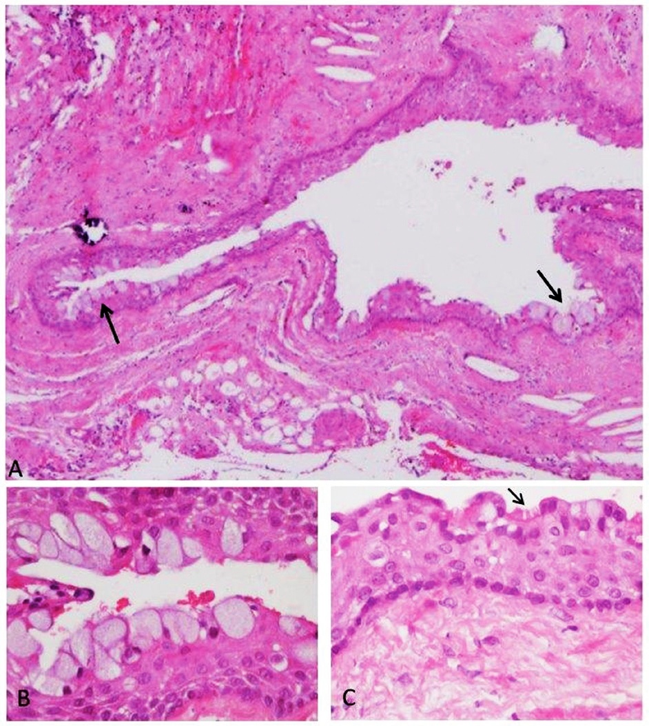
The source demonstrates metaplastic epithelial changes in a radicular-cyst wall. These are selected examples, not a description of every radicular cyst. Interpret unusual lining features with the rest of the architecture and the clinical relationship to the teeth.
Panel key
- A
- Cyst wall with mucous-cell changes.
- B
- Higher-power view of mucous cells.
- C
- Ciliated epithelial cells, marked by the source arrow.
Histopathology of a periapical cyst, with metaplastic changes of mucous secreting cells, and ciliated cells.jpg · Igor Tsesis, Eyal Rosen, Liz Dubinsky, Amos Buchner and Marilena Vered · CC BY 2.5. Reproduced without alteration. Labels, arrows and circles, where present, belong to the source image. Original publication.
Do mucous cells alone establish a glandular odontogenic cyst?
No. Mucous-cell metaplasia can occur in other cysts. Classification requires the complete histological pattern and clinical correlation.
Radiographic anatomy
Orient yourself on real dental radiographs. Read the caption before drawing conclusions from an example image.
Panoramic anatomy with unerupted third molars
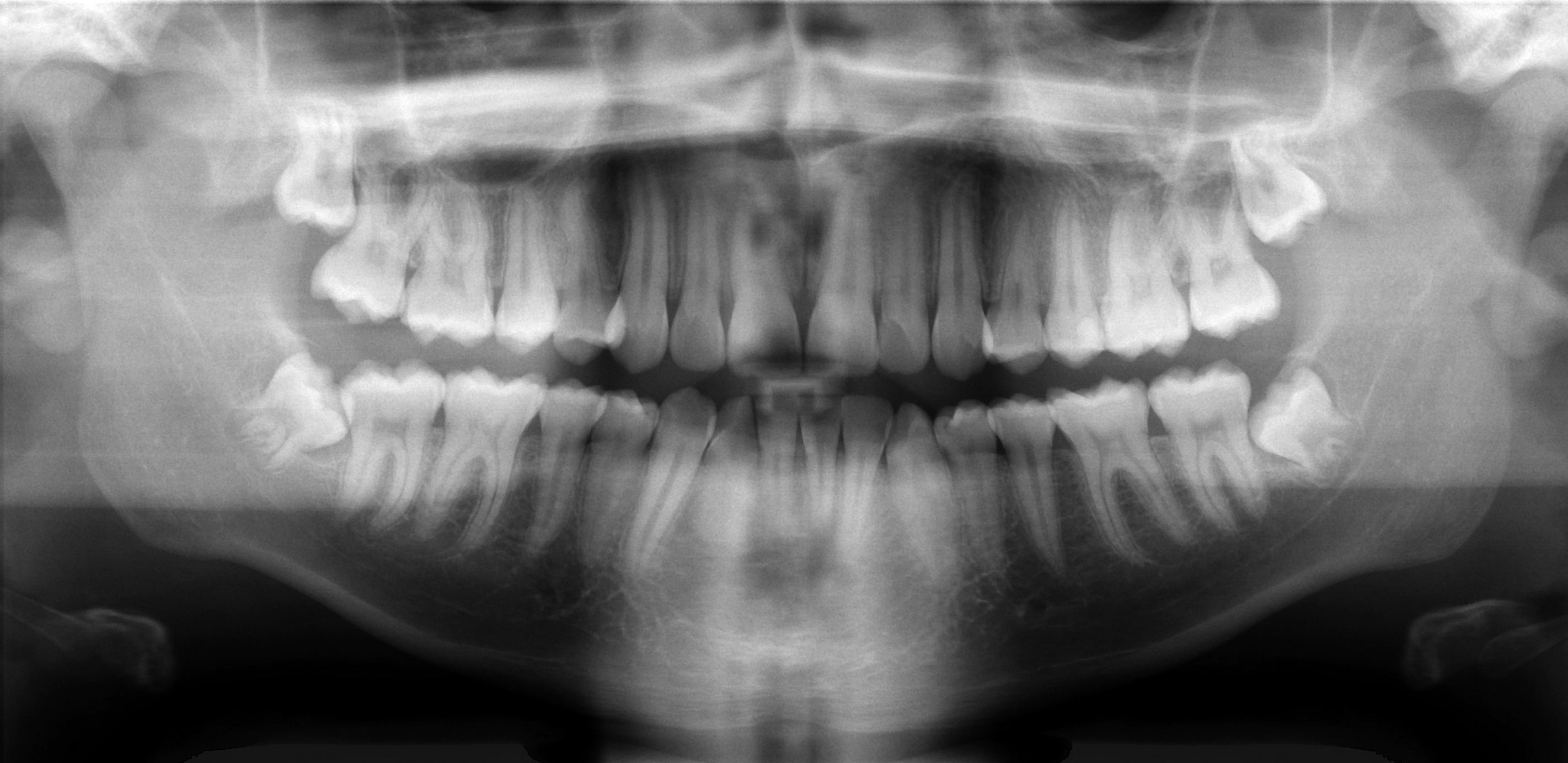
Scan the whole image systematically: compare both sides, trace the mandibular borders and canals, inspect the maxillary sinuses and count the teeth. This published example includes unerupted third molars; it is not an all-normal reference. Radiographic overlap alone cannot establish the three-dimensional nerve–root relationship.
Basic panoramic radiograph.jpg · Coronation Dental Specialty Group · CC BY 3.0. None; original image reproduced without alteration.
Can a panoramic image alone prove whether roots touch the inferior alveolar nerve?
No. It is a two-dimensional projection. Interpret the signs in clinical context, and request further imaging only when justified by a management question.
Mixed dentition on a panoramic radiograph
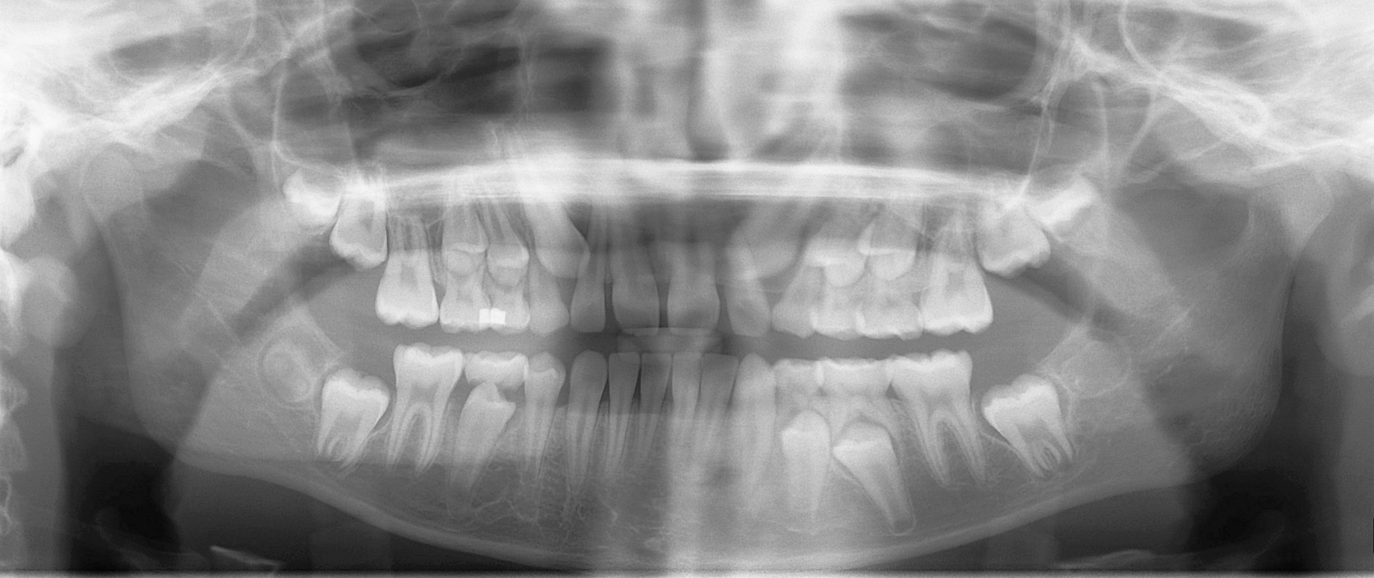
Distinguish erupted permanent teeth, retained primary teeth and unerupted successors. Compare development on the two sides and account for every permanent tooth. This is one published example of mixed dentition, not a fixed age-based template for every child.
Mixed dentition pan.jpg · Coronation Dental Specialty Group · CC BY 3.0. None; original image reproduced without alteration.
Which permanent teeth erupt without replacing primary teeth?
The permanent molars. Premolars replace the primary molars; permanent incisors and canines replace their primary predecessors.
Head and neck anatomy
Follow the structures behind clinical examination, movement, sensation and local anaesthesia.
Major salivary glands
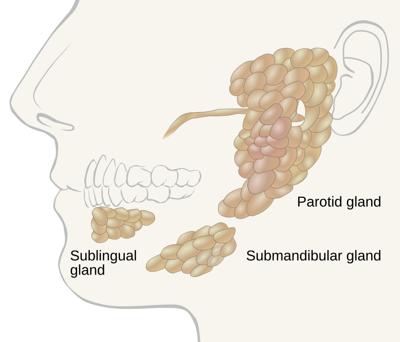
Locate the parotid, submandibular and sublingual glands. Use the gland distribution to relate swelling to the history; the diagram alone does not establish the cause of a mass.
Salivary glands labeled.svg · Goran tek-en, following request by and knowledge from Tom (LT) · CC BY-SA 4.0. None; reproduced without alteration.
Which major gland sits in the anterior floor of the mouth?
The sublingual gland. The submandibular duct also opens into the anterior floor of the mouth, near the lingual frenulum.
Temporomandibular joint anatomy
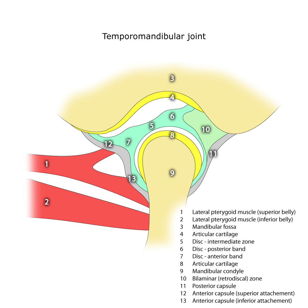
Identify the mandibular condyle, articular disc, articular eminence and mandibular fossa. The disc separates the upper and lower joint compartments.
Temporomandibular joint.png · Frank Gaillard · CC BY-SA 3.0. None; reproduced without alteration.
In which compartment does the main translational movement occur?
The superior compartment. Rotation predominantly occurs in the inferior compartment; normal opening combines both movements.
Adult mandible: labelled lateral anatomy
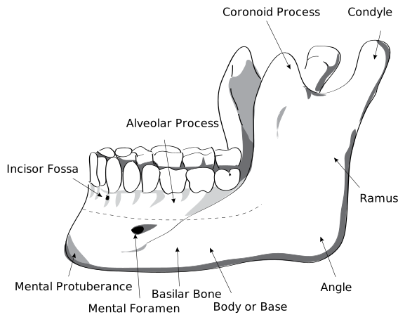
Locate the body, ramus, angle, condylar process, coronoid process and mental foramen. Use the labels to distinguish the two superior processes and the landmarks relevant to local anaesthesia and surgery.
HumanMandibleLeft.svg · Djexplo · CC0. None; reproduced without alteration.
Which nerve emerges through the mental foramen?
The mental nerve, a terminal branch of the inferior alveolar nerve, supplying the lower lip and chin.
Cervical lymph nodes and anatomical levels
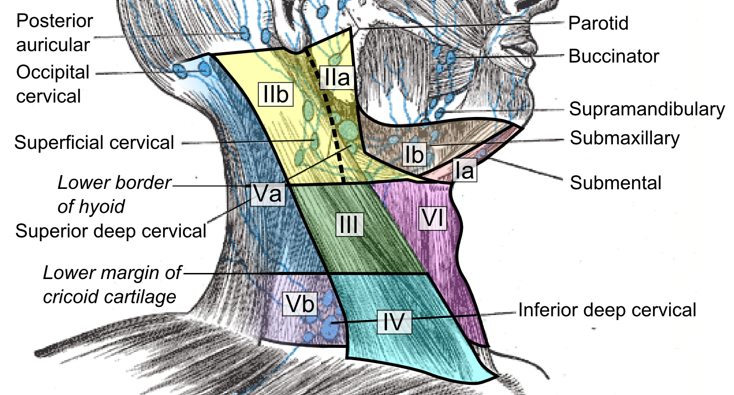
Compare the named node groups with the numbered cervical levels. This schematic does not replace cross-sectional imaging criteria for staging or treatment planning.
Cervical lymph nodes and levels.png · Mikael Häggström, M.D. · CC0. None; reproduced without alteration.
What should you record about a clinically palpable cervical node?
Its exact site and laterality, size, tenderness, consistency and mobility, alongside the relevant oral examination and history.
Trigeminal nerve & dental branches
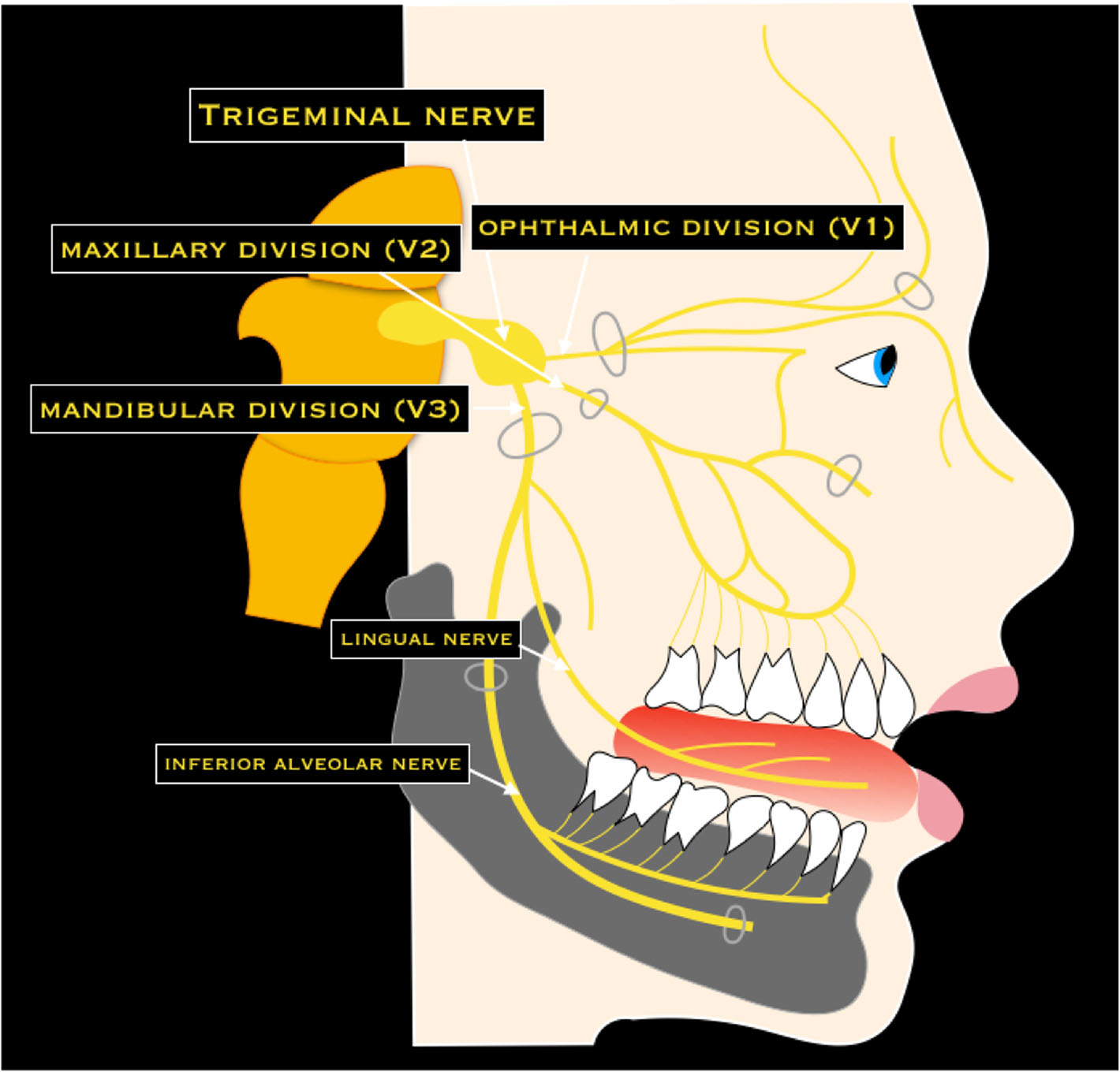
Trace V1, V2 and V3, then the lingual and inferior alveolar nerves. Connect each to the sensory examination after lower third-molar surgery. This is a branch overview, rather than an injection-placement diagram.
Trigeminal nerve & dental branches · Nicola Romano, Margherita Federici and Antonio Castaldi · CC BY 4.0. Original image; displayed at a responsive size. Original publication.
Skull base & cranial foramina
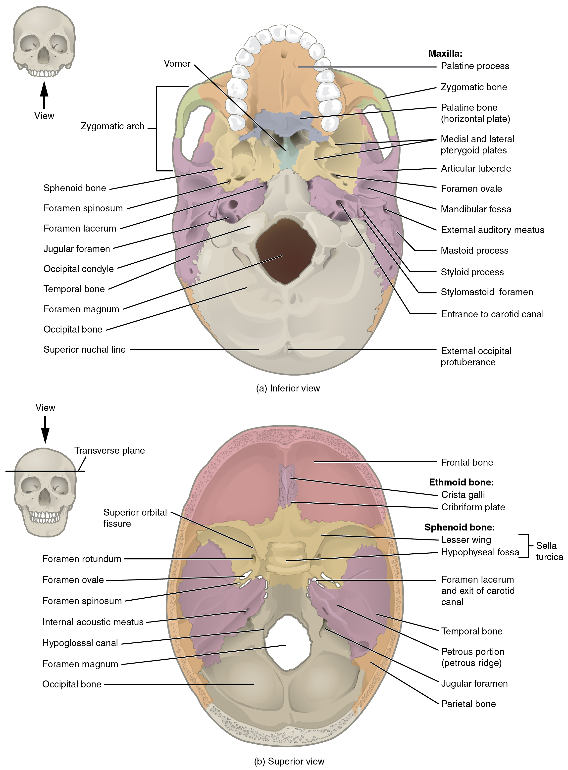
Find the superior orbital fissure, foramen rotundum and foramen ovale, and recall which trigeminal division uses each. Compare the palate, pterygoid plates and mandibular fossa in the inferior view.
Skull base & cranial foramina · OpenStax College · CC BY 3.0. Original image; displayed at a responsive size. Original publication.
Mandibular landmarks
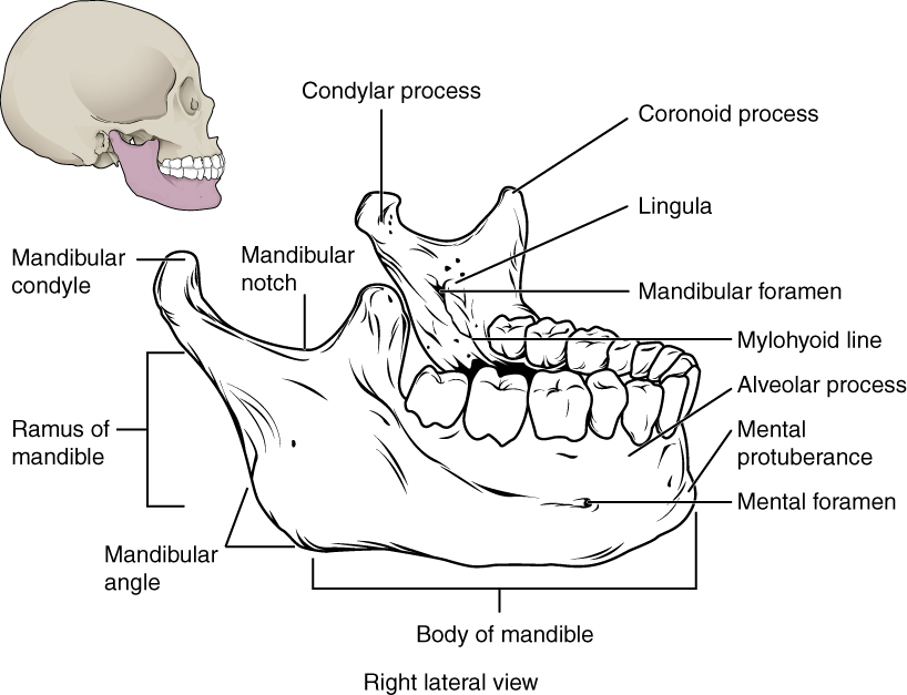
Locate the mental and mandibular foramina, lingula and mylohyoid line. The mandibular foramen, lingula and mylohyoid line are medial landmarks; this schematic brings several surfaces together. Relate the landmarks to nerve risk and fracture assessment.
Mandibular landmarks · OpenStax College · CC BY 3.0. Original image; displayed at a responsive size. Original publication.
Temporomandibular joint
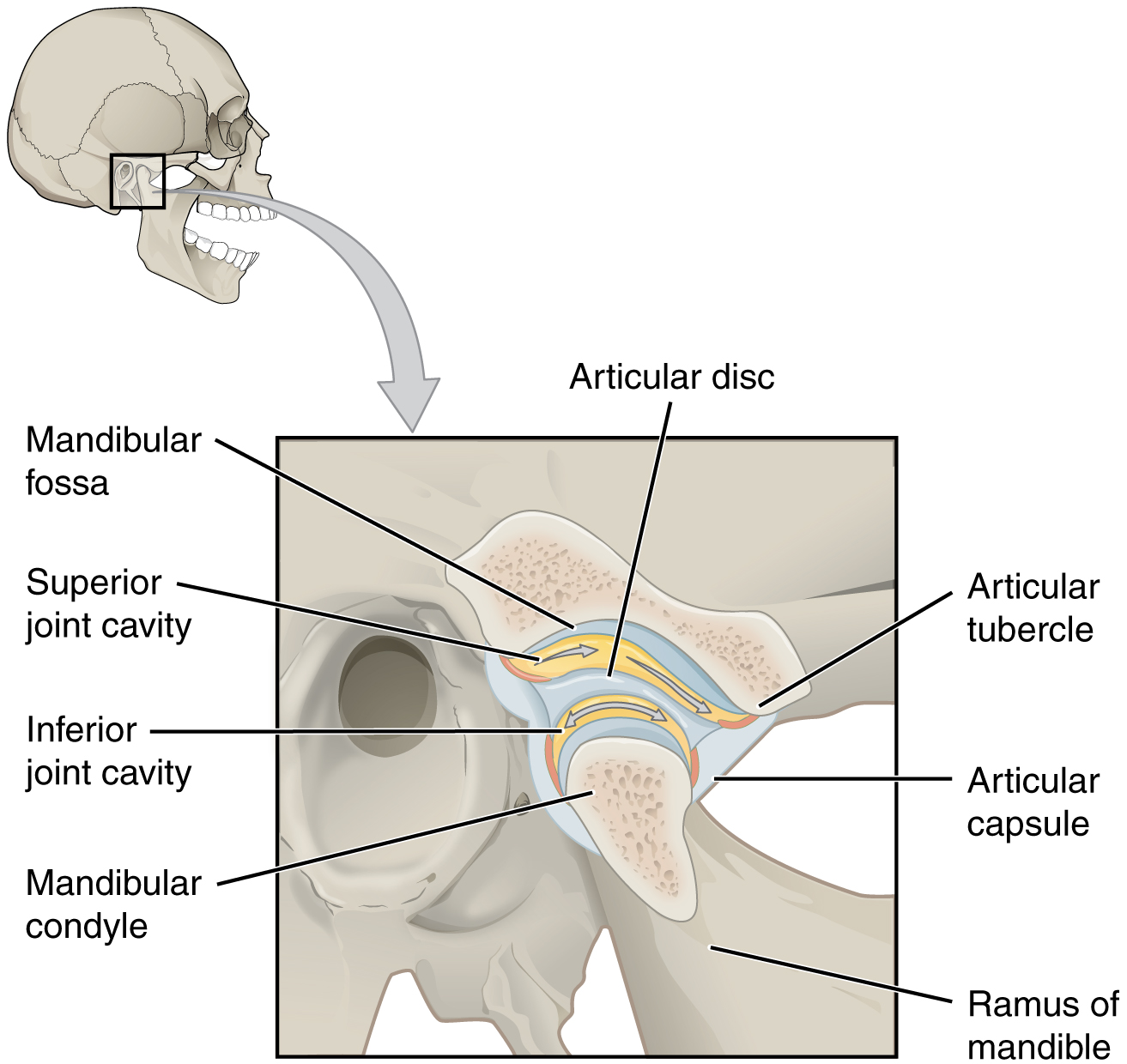
Identify the disc and the two joint compartments. Recall rotation versus translation, then connect the condyle and articular tubercle to dislocation and the disc to TMD assessment.
Temporomandibular joint · OpenStax College · CC BY 3.0. Original image; displayed at a responsive size. Original publication.
Major salivary glands & ducts
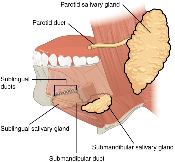
Name each gland and its duct opening. Relate duct obstruction to meal-related swelling and the sublingual gland to a ranula. This overview does not depict every lingual-nerve or facial-nerve relationship.
Major salivary glands & ducts · OpenStax College · CC BY 3.0. Original image; displayed at a responsive size. Original publication.
Head and neck lymphatic glands (Gray's Anatomy, plate 602)
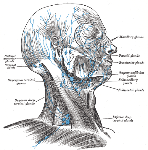
Find the submental and submandibular groups and follow drainage toward the cervical nodes. In this historical figure, ‘glands’ means lymph nodes and ‘submaxillary’ means submandibular. Use current cancer guidance for modern oncological neck levels.
Head and neck lymphatic glands (Gray's Anatomy, plate 602) · Henry Vandyke Carter; reproduced in Henry Gray, Anatomy of the Human Body (1918), plate 602 · Public domain. Unchanged published image; displayed responsively.
Suprahyoid and infrahyoid muscles
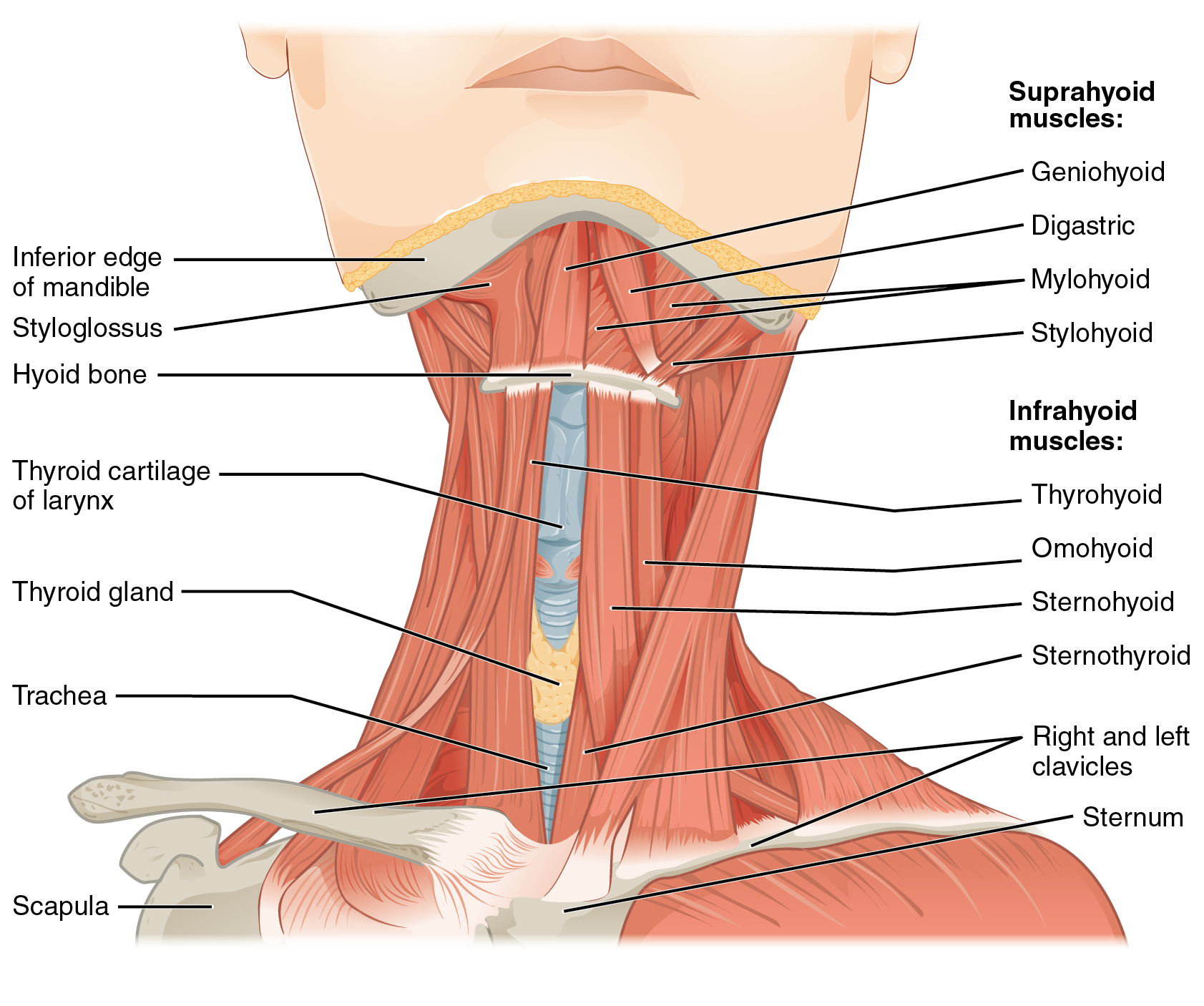
Locate the hyoid, then the four suprahyoid muscles. The mylohyoid forms the muscular floor of the mouth; the geniohyoid lies above it. Relate these muscles to swallowing, mandibular depression and the sublingual–submandibular boundary. The figure shows selected layers exposed for teaching.
1110 Muscle of the Anterior Neck.jpg · OpenStax · CC BY 4.0. None; original image reproduced without alteration.
Which muscle forms the main muscular floor of the mouth?
Mylohyoid. Geniohyoid lies superior to it; the anterior belly of digastric lies inferior to it.
Extrinsic tongue muscles and surface landmarks
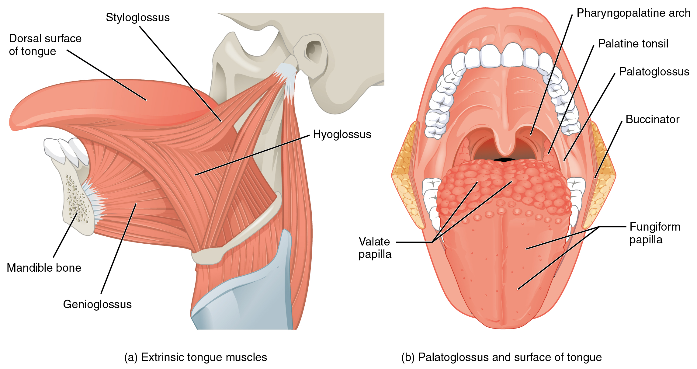
Follow genioglossus from the mandible, hyoglossus from the hyoid and styloglossus from the styloid region. The second view shows palatoglossus and tongue surface landmarks. “Pharyngopalatine arch” is the palatopharyngeal arch; “valate” in the original refers to vallate papillae.
1109 Muscles that Move the Tongue.jpg · OpenStax · CC BY 3.0. None; original image reproduced without alteration.
Which extrinsic tongue muscle is the exception to hypoglossal motor supply?
Palatoglossus, which is supplied through the pharyngeal plexus by the vagus nerve. The other extrinsic tongue muscles receive hypoglossal supply.
The four muscles of mastication
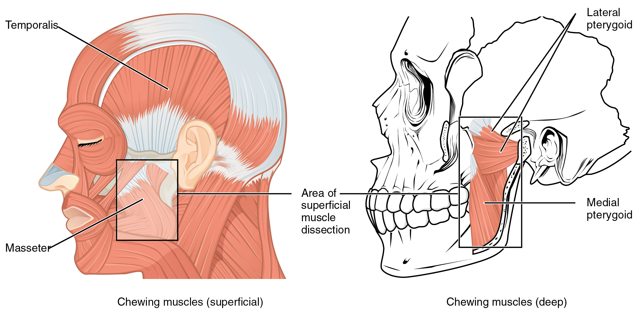
Identify temporalis and masseter in the superficial view, then both pterygoid muscles in the deeper view. Use the lines of pull to explain mandibular elevation, protrusion and side-to-side movement. All four receive motor supply from the mandibular division of the trigeminal nerve.
1108 Muscle that Move the Lower Jaw.jpg · OpenStax · CC BY 4.0. None; original image reproduced without alteration.
Which division of the trigeminal nerve supplies the muscles of mastication?
The mandibular division, V3. Do not confuse this with the facial nerve supply to the muscles of facial expression.
Soft-palate and pharyngeal muscles: posterior view
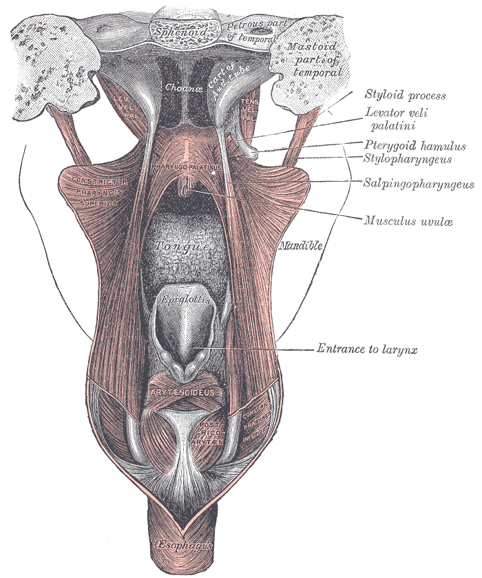
Find levator veli palatini and the tensor tendon turning around the pterygoid hamulus. This posterior view also shows the pharyngeal wall and laryngeal entrance. The historical label “pharyngo-palatinus” denotes palatopharyngeus.
Gray1028.png · Henry Vandyke Carter; reproduced in Gray’s Anatomy (1918), plate 1028 · Public domain. None; original image reproduced without alteration.
Which soft-palate muscle has mandibular nerve supply?
Tensor veli palatini, supplied by V3 through the nerve to medial pterygoid. The other principal palatal muscles receive vagal supply through the pharyngeal plexus.
Tongue muscle architecture in coronal section
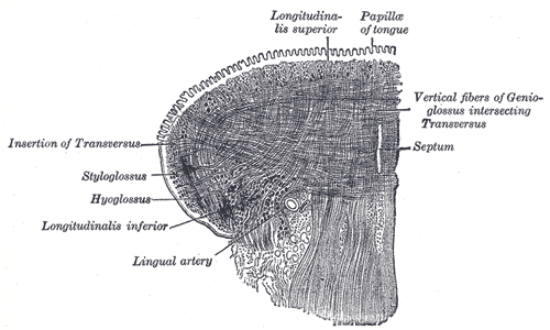
Trace the longitudinal and transverse fibres around the lingual septum. The original also labels vertical fibres of genioglossus, an extrinsic muscle; this is not a diagram of intrinsic muscles alone. Intrinsic fibres principally change tongue shape, while extrinsic muscles reposition it.
Gray1020.png · Henry Vandyke Carter; reproduced in Gray’s Anatomy (1918), plate 1020 · Public domain. None; original image reproduced without alteration.
How do intrinsic and extrinsic tongue muscles differ functionally?
Intrinsic muscles primarily change tongue shape. Extrinsic muscles primarily move the tongue as a whole; coordinated movements recruit both groups.
Cranial nerves at the base of the brain
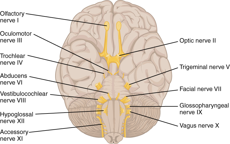
Orientate the inferior brain surface, then locate V, VII, IX, X and XII. Connect them to facial sensation and mastication, facial expression, swallowing and palatal function, and tongue movement. This is a brain-surface overview, rather than a map of the skull foramina.
1320 The Cranial Nerves.jpg · OpenStax · CC BY 4.0. None; original image reproduced without alteration.
Which cranial nerve principally controls tongue movement?
The hypoglossal nerve, XII. Palatoglossus is the exception among the tongue muscles and is supplied through the vagus nerve.
Maxillary and mandibular dental nerve branches
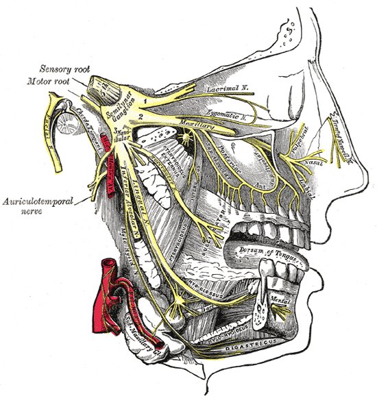
Follow V2 toward the upper teeth and V3 toward the lingual and inferior alveolar nerves. The original terms “inferior dental” and “submaxillary ganglion” correspond to inferior alveolar nerve and submandibular ganglion. This shows anatomy; it does not specify a safe needle trajectory.
Gray778.png · Henry Vandyke Carter; reproduced in Gray’s Anatomy (1918), plate 778 · Public domain. None; original image reproduced without alteration.
Which nerve continues through the mental foramen?
The mental branch of the inferior alveolar nerve, providing sensation to the lower lip and chin. The incisive branch continues within the mandible.
Palatal development: historical embryo view
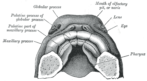
Find the paired palatal processes and the anterior intermaxillary region. The historical labels use “globular process”; interpret these with current descriptions of the medial nasal prominences and primary palate. Use the chapter for modern developmental timing and fusion terminology.
Gray50.png · Henry Vandyke Carter, after His; reproduced in Gray’s Anatomy (1918), plate 50 · Public domain. None; original image reproduced without alteration.
Which structures form the secondary palate?
The paired lateral palatal shelves, arising from the maxillary prominences, elevate and fuse with each other and with the primary palate and nasal septum.
Development and histology
Connect tissue structure, tooth development and the changing dentition.
Tooth development: cap, bell and root formation
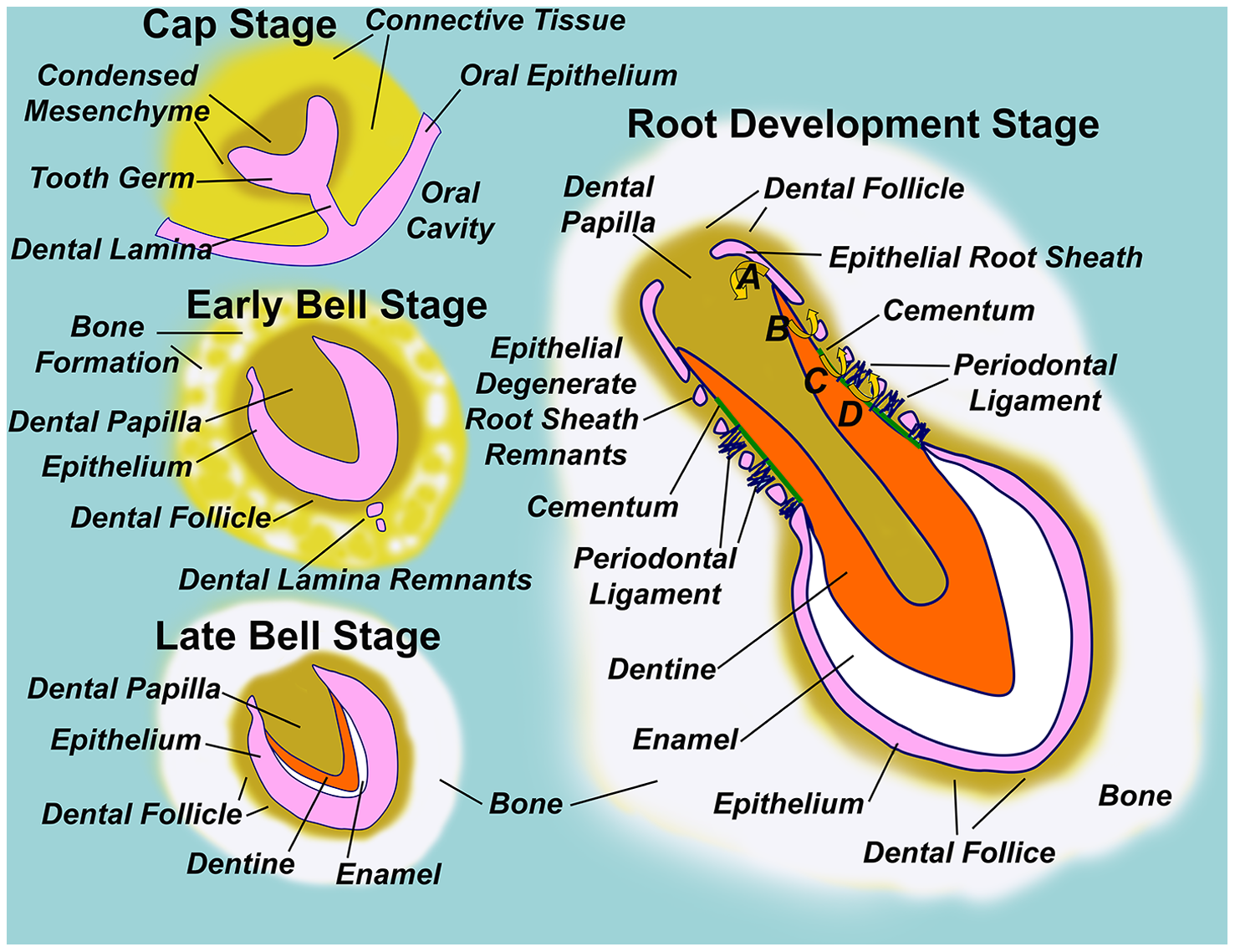
Follow the dental lamina, enamel organ, dental papilla and dental follicle through development. Locate the epithelial root sheath in the root-development panel.
Diagram illustrating normal tooth formation.png · Sarrafpour B, Swain M, Li Q, Zoellner H · CC BY 4.0. None; reproduced without alteration.
Which structure gives rise to dentine and pulp?
The dental papilla. The enamel organ gives rise to enamel; the dental follicle contributes to supporting periodontal tissues.
The pulp–dentine interface
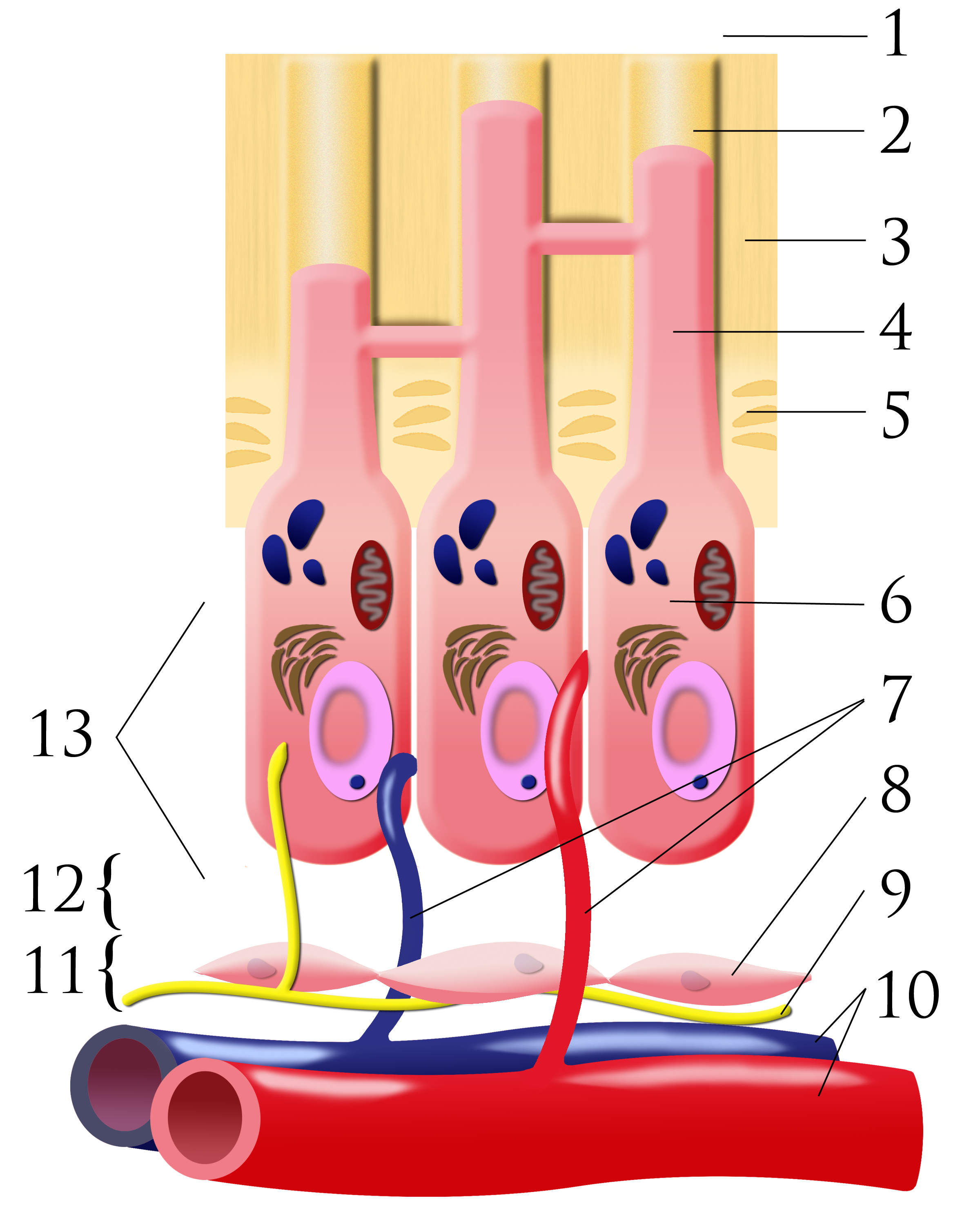
Number key: 1 outer-tooth direction; 2 dentinal tubule; 3 dentine; 4 odontoblastic process; 5 predentine; 6 odontoblast; 7 capillaries; 8 fibroblasts; 9 nerve; 10 artery and vein; 11 cell-rich zone; 12 cell-poor zone; 13 pulp chamber. This is a conceptual schematic, not a scale histological section.
Pulpal dentin junction.png · Ian Furst · CC BY-SA 3.0. None; original image reproduced without alteration.
Which cells form dentine, and where are their cell bodies?
Odontoblasts form dentine. Their cell bodies line the pulp–dentine border, with processes extending into dentinal tubules.
Occlusion and orthodontics
Compare dental relationships and recognise the features used in orthodontic assessment.
Overjet and overbite
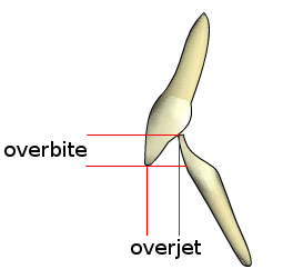
Overjet describes the horizontal relationship between the incisors; overbite describes their vertical overlap. Record the magnitude, direction and whether the overbite is complete or incomplete. The schematic is not drawn to a clinical measurement scale.
Overjet-overbite.png · Nielson2000 · CC BY-SA 3.0. None; original image reproduced without alteration.
Which measurement is horizontal: overjet or overbite?
Overjet is horizontal. Overbite is the vertical overlap of the incisors.
Class II division 1: relationship schematic
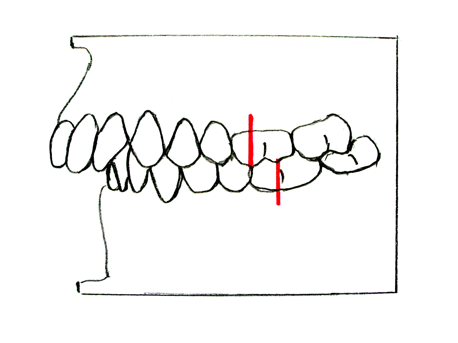
Compare the posterior molar relationship with the upper-incisor inclination and increased overjet. The red reference marks demonstrate the Class II molar relationship. Describe the incisor relationship separately from the molar and skeletal relationships in a clinical assessment.
Zahnfehlstellung Angle-Klasse II-1.jpg · Dr. Georg Risse · CC BY-SA 3.0. None; original image reproduced without alteration.
What upper-incisor feature typically distinguishes Class II division 1 from division 2?
Division 1 usually has proclined or normally inclined upper incisors with increased overjet; division 2 has retroclined upper central incisors.
Class II division 2: relationship schematic
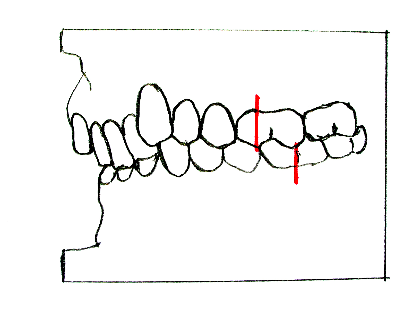
Identify the retroclined upper incisors and deep overlap, then compare the molar references with the division 1 schematic. A Class II molar relationship does not by itself specify the incisor division or establish the skeletal diagnosis.
Zahnfehlstellung Angle-Klasse II-2.jpg · Dr. Georg Risse · CC BY-SA 3.0. None; original image reproduced without alteration.
Does a Class II molar relationship alone tell you the incisor division?
No. Assess the upper central-incisor inclination and incisor relationship separately; document skeletal and soft-tissue findings as well.
Class III: relationship schematic
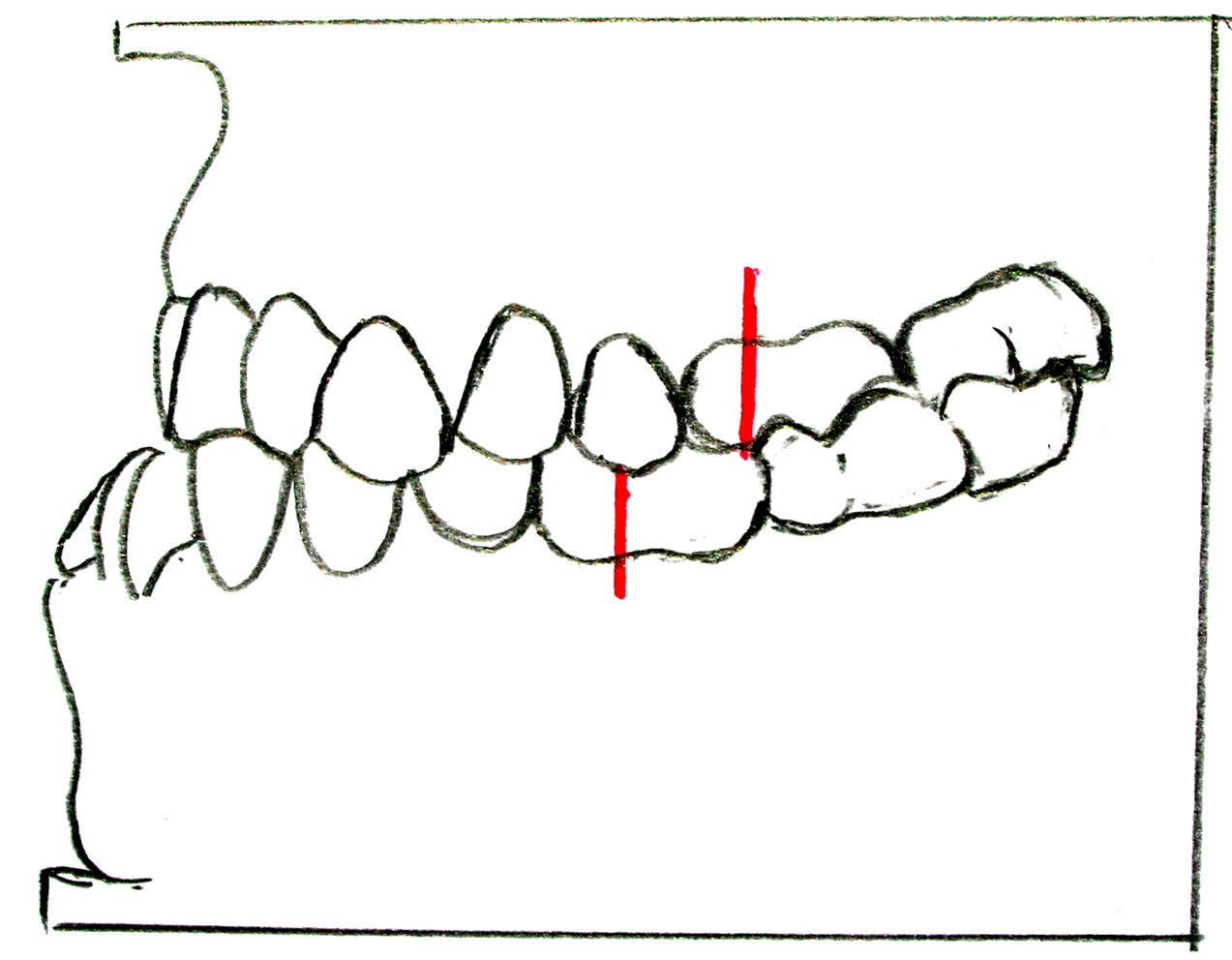
Compare the molar reference points with the Class II diagrams. The anterior relationship shown is a reverse overjet. A dental Class III relationship is not automatically proof of a skeletal Class III pattern: examine the facial profile and any functional displacement.
Zahnfehlstellung Angle-Klasse III.jpg · Dr. Georg Risse · CC BY-SA 3.0. None; original image reproduced without alteration.
Why assess the mandible on closure when a child has an anterior crossbite?
A functional forward displacement can create or exaggerate an apparent Class III relationship and influences diagnosis and referral.
Oral tissues and clinical science
Use these references alongside the detailed chapters to connect appearance with the underlying process.
Tooth structure and supporting tissues
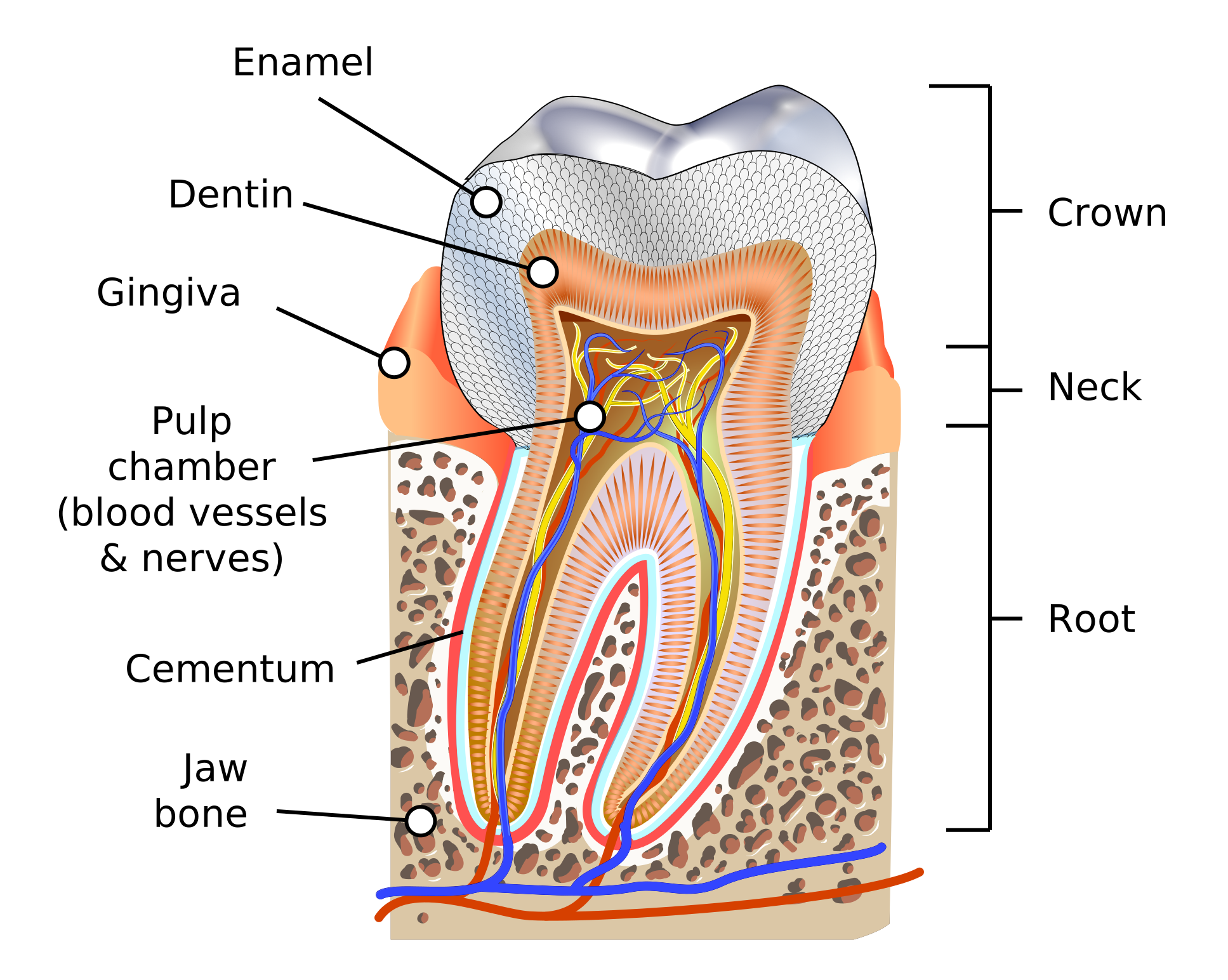
Identify enamel, dentine, pulp, cementum, periodontal ligament and alveolar bone. Trace the pulp chamber towards the root canals and apex.
Human tooth diagram-en.svg · K. D. Schroeder (KDS4444) · CC BY-SA 4.0. None; reproduced without alteration.
Which tissue links the root surface to alveolar bone?
The periodontal ligament; cementum covers the root and provides a surface for fibre attachment.
Trigeminal divisions and facial sensory territories
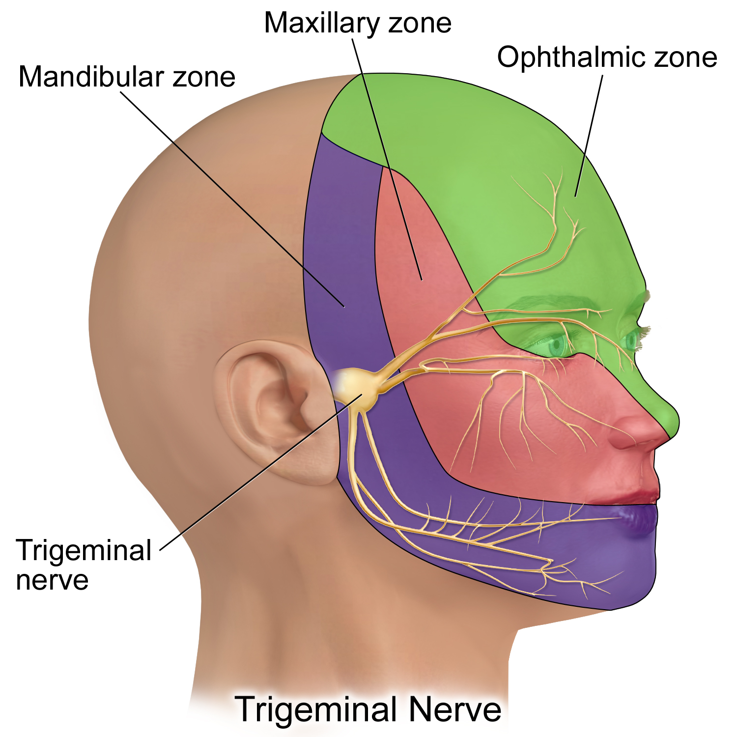
V1 is ophthalmic, V2 maxillary and V3 mandibular. This is a schematic sensory territory map, not a detailed map of every peripheral branch; V3 also carries motor fibres.
Trigeminal Nerve.png · BruceBlaus · CC BY-SA 4.0. None; reproduced without alteration.
Which division gives rise to the inferior alveolar and lingual nerves?
The mandibular division, V3. Distinguish lower lip/chin sensory change from altered tongue sensation.
Gingivitis: inflamed gingiva without attachment loss
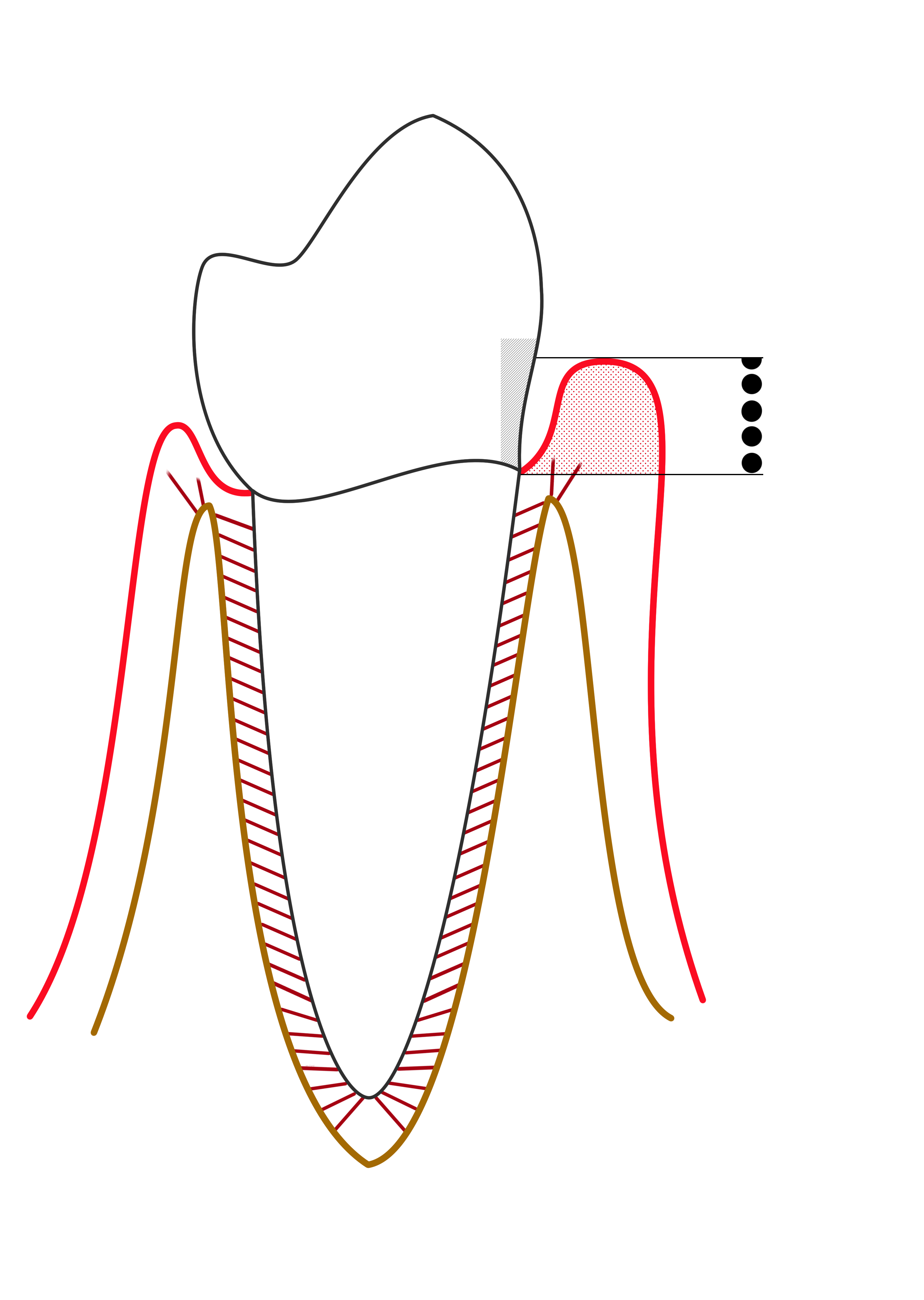
The red marginal outline represents gingival inflammation. Compare the gingival margin, sulcus and supporting bone with the periodontitis diagram. The probe-scale dots illustrate depth, not a diagnosis by themselves.
Line diagram of Gingivitis.png · Ian Furst · CC BY-SA 4.0. None; reproduced without alteration.
Does gingival bleeding alone establish periodontitis?
No. Periodontitis requires evidence of supporting attachment loss, interpreted with clinical and radiographic findings.
Periodontitis: pocket formation and loss of support
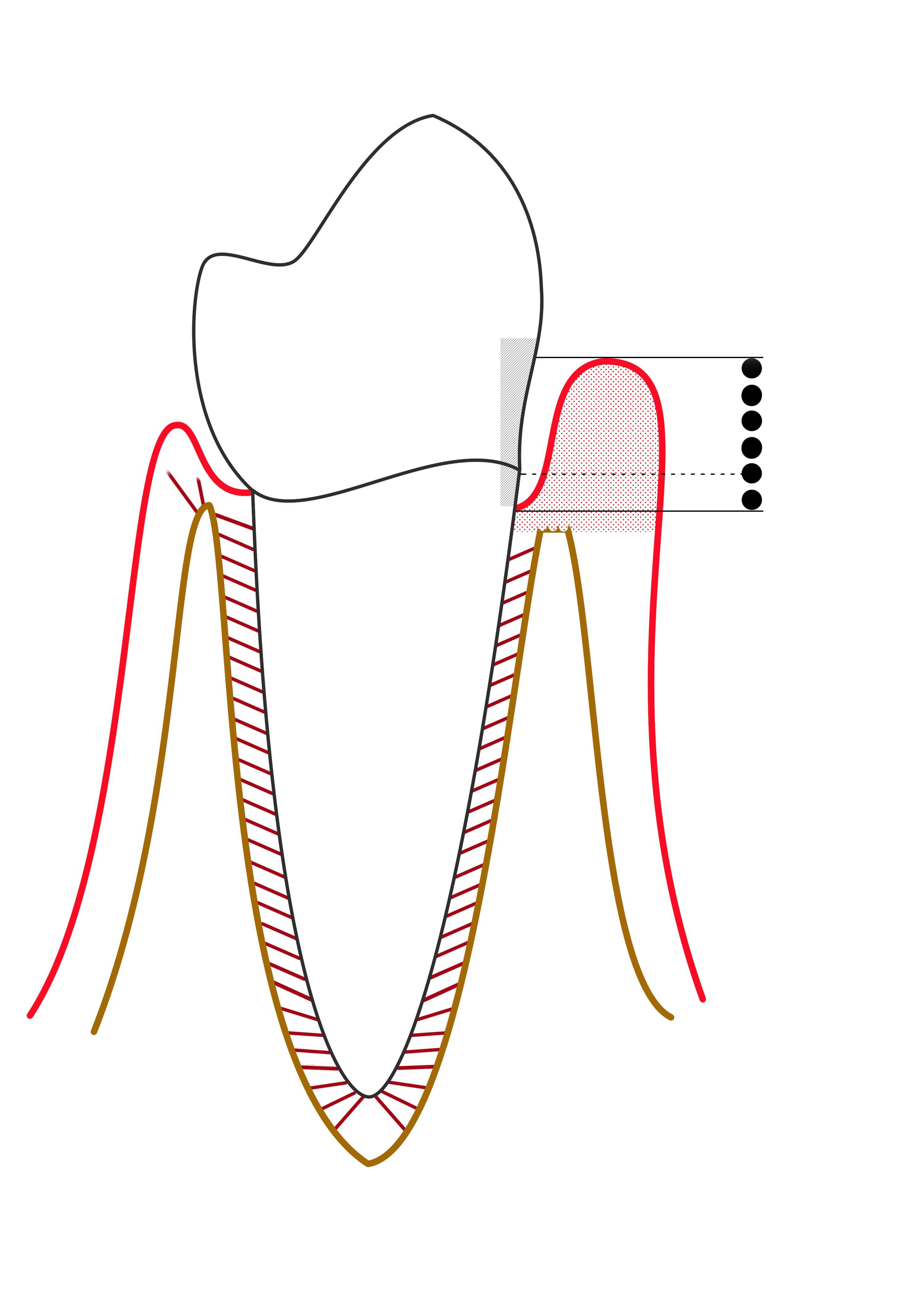
Compare the apical extent of the pocket and the reduced supporting bone on the affected side. This simplified diagram is labelled “mild periodontitis” by its author; it is not a modern stage/grade classification chart.
Mild periodontitis.png · Ian Furst · CC BY-SA 4.0. None; reproduced without alteration.
Why is probing depth different from clinical attachment level?
Probing depth runs from the gingival margin to the pocket base. Clinical attachment level uses the cemento-enamel junction as its reference; recession or enlargement changes their relationship.
Head & neck arterial supply
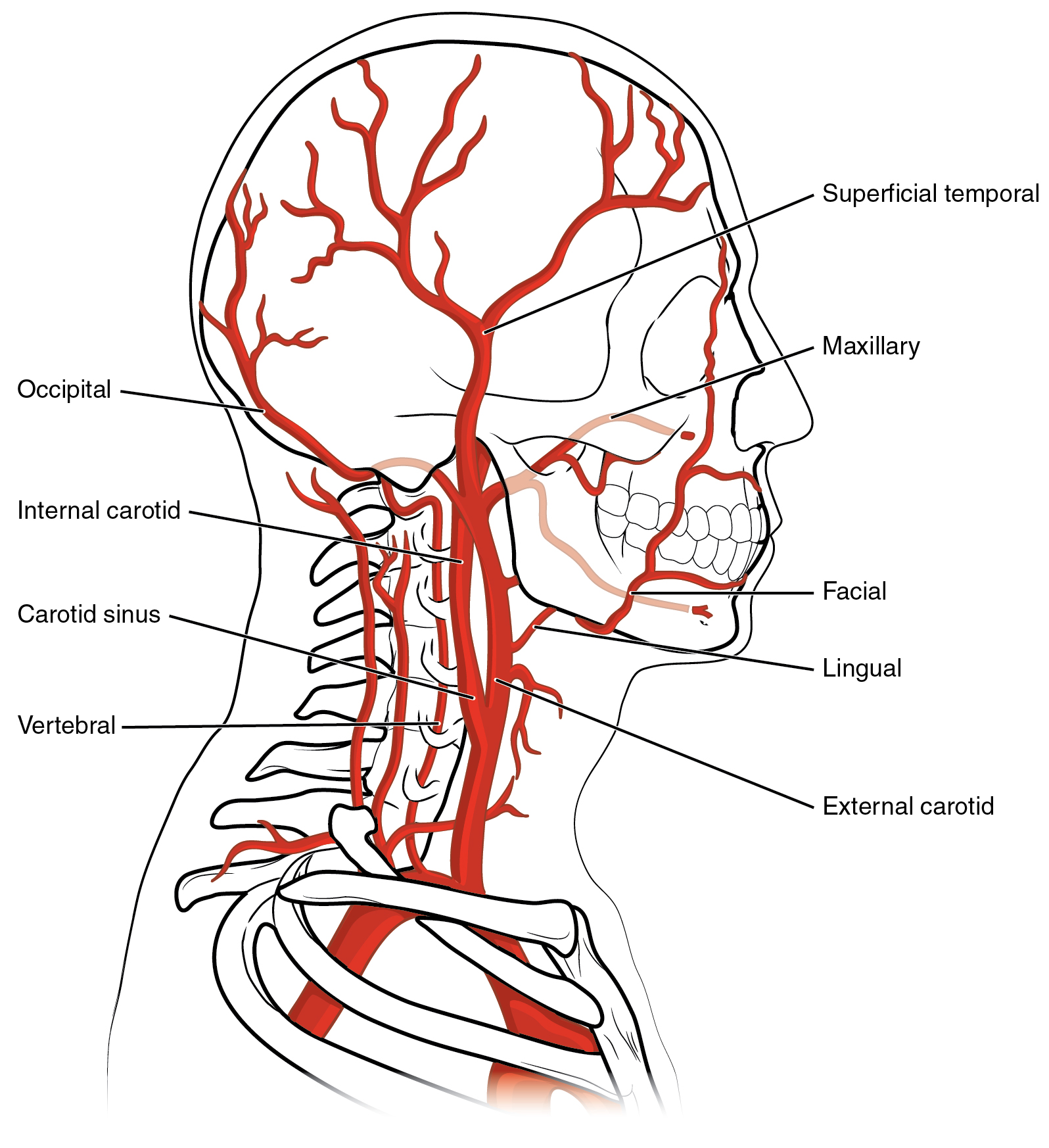
Trace the facial, lingual, maxillary and superficial temporal arteries back to the external carotid. Relate the facial and maxillary vessels to the operative anatomy discussed in the notes.
Head & neck arterial supply · OpenStax College · CC BY 3.0. Original image; displayed at a responsive size. Original publication.
Tooth & supporting tissues
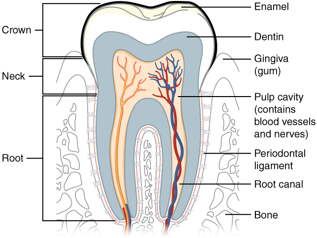
Trace the pulp and root canal to the apical region, then identify the periodontal ligament and supporting bone. Relate these structures to avulsion, apical pathology and extraction. The original uses the spelling “dentin”; cementum is not separately labelled.
Tooth & supporting tissues · OpenStax College · CC BY 3.0. Original image; displayed at a responsive size. Original publication.
Stages of secondary bone healing
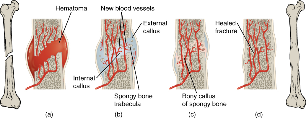
Follow haematoma, callus formation and remodelling. This general secondary-fracture-healing model uses a long bone; it is not an extraction-socket diagram or a depiction of primary healing under rigid fixation.
Stages of secondary bone healing · OpenStax College · CC BY 3.0. Original image; displayed at a responsive size. Original publication.
Coronal sublingual and submandibular spaces with normal MRI correlation
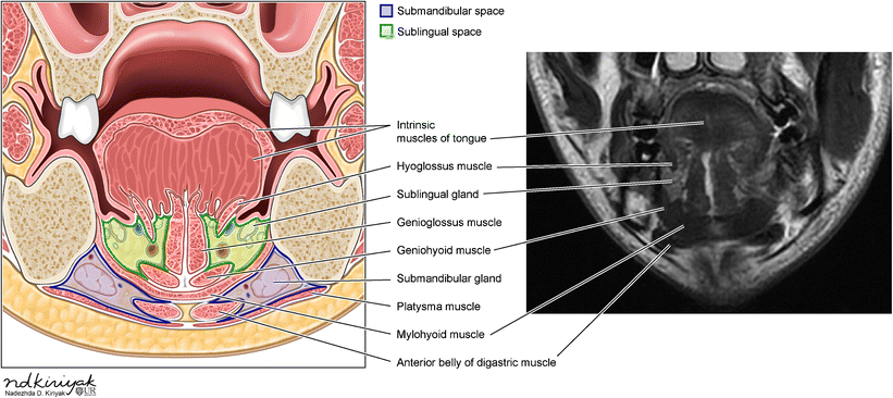
Identify the mylohyoid and compare the sublingual and submandibular compartments in the schematic and normal MRI. Relate the compartments to the tooth-apex relationships discussed in this section.
Coronal sublingual and submandibular spaces with normal MRI correlation · Swapnil Patel and Alok A. Bhatt (2018); illustration credited within the figure to Nadezhda D. Kiriyak / University of Rochester · CC BY 4.0. Unchanged published image; displayed responsively. Original publication.
Neuromuscular junction
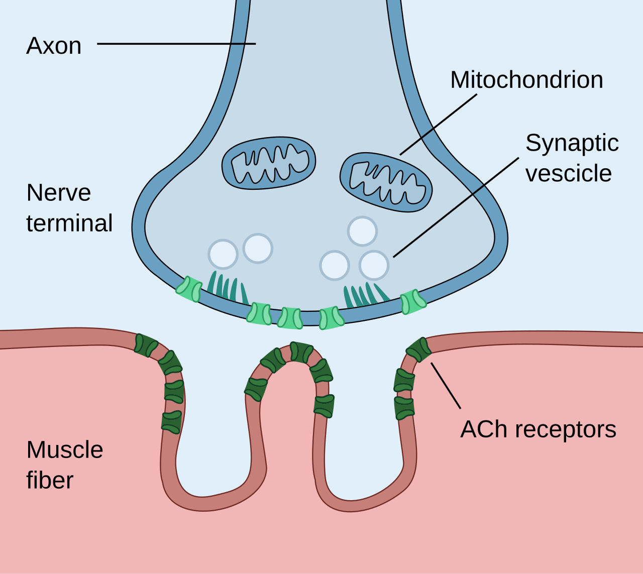
Follow acetylcholine release from the motor nerve terminal to postsynaptic receptors. Connect this synapse to neuromuscular blockers; compare it with axonal sodium-channel blockade in the local-anaesthesia lesson.
Neuromuscular junction · Paul Hege (own work, 2020) · CC BY-SA 4.0. Unchanged published raster preview; displayed responsively. Original available from the source.
Stages and threshold of an action potential
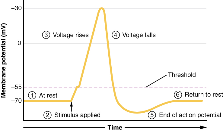
Trace threshold, depolarisation, repolarisation and after-hyperpolarisation. Recall sodium-channel opening during the rising phase and relate sodium-channel blockade to local anaesthesia. The plotted voltages illustrate a representative cell.
Stages and threshold of an action potential · OpenStax (Anatomy and Physiology, 2016 version) · CC BY 4.0. Unchanged published image; displayed responsively. Original publication.
Vascular spasm, platelet plug and blood-clotting cascade
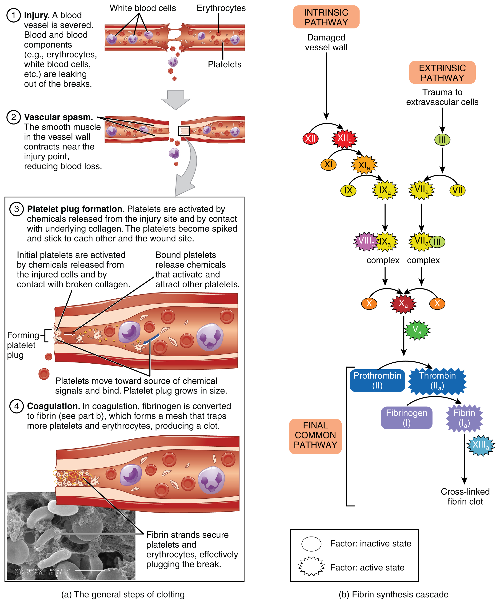
Compare platelet adhesion and plug formation with the development of a fibrin-stabilised clot. Use the labelled intrinsic, extrinsic and common pathways to revise factor deficiencies and laboratory tests. The cascade simplifies the more interconnected process in vivo.
Vascular spasm, platelet plug and blood-clotting cascade · OpenStax College (2013); source micrograph credited to Kevin MacKenzie · CC BY 3.0. Unchanged published image; displayed responsively. Original publication.
Inflammation, granulation and maturation in tissue repair
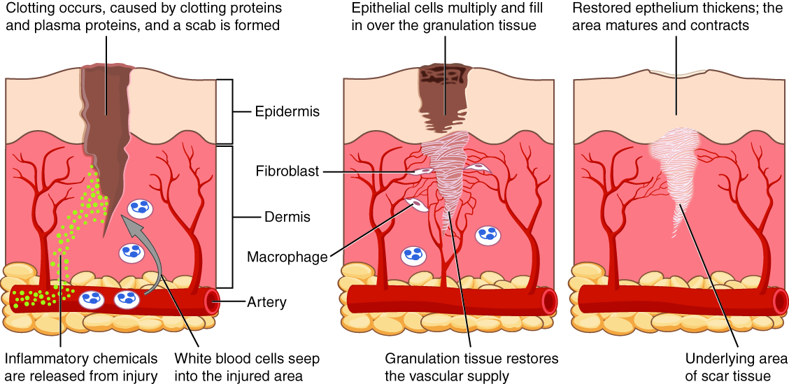
Relate inflammatory cells, fibroblasts, granulation tissue, epithelialisation and scar maturation to the overlapping stages of wound healing. This is a skin-wound example, not an extraction socket; oral mucosa differs and does not necessarily form a dry scab. Healing phases overlap.
Inflammation, granulation and maturation in tissue repair · OpenStax College (2013) · CC BY 3.0. Unchanged published image; displayed responsively. Original publication.
Oral mucosa: epithelium, basement membrane and lamina propria
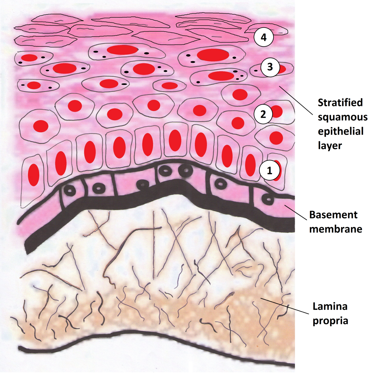
Identify the epithelium, basement membrane and lamina propria. Relate the epithelial–stromal interface to in-situ disease and invasion. This drawing represents a keratinising surface; oral sites have different keratinisation patterns. Use the printed anatomical names for revision.
Oral mucosa: epithelium, basement membrane and lamina propria · Wiki-minor (own work, 2011) · CC BY-SA 3.0. Unchanged published raster preview; displayed responsively. Original available from the source.
Osteoclast resorption and osteoblast formation during bone remodelling
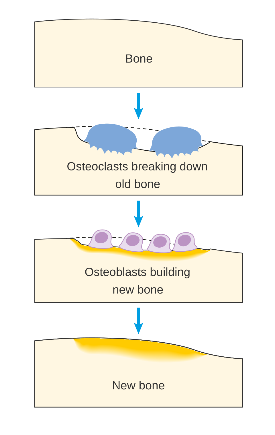
Follow osteoclast resorption and osteoblast replacement, then connect the cycle to antiresorptive therapy and MRONJ. Add osteocyte regulation and the RANK–RANKL–OPG system to this simplified sequence.
Osteoclast resorption and osteoblast formation during bone remodelling · Cancer Research UK (2014; source revision 2016) · CC BY-SA 4.0. Unchanged published raster preview; displayed responsively. Original available from the source.
Larynx: anterior and right lateral views
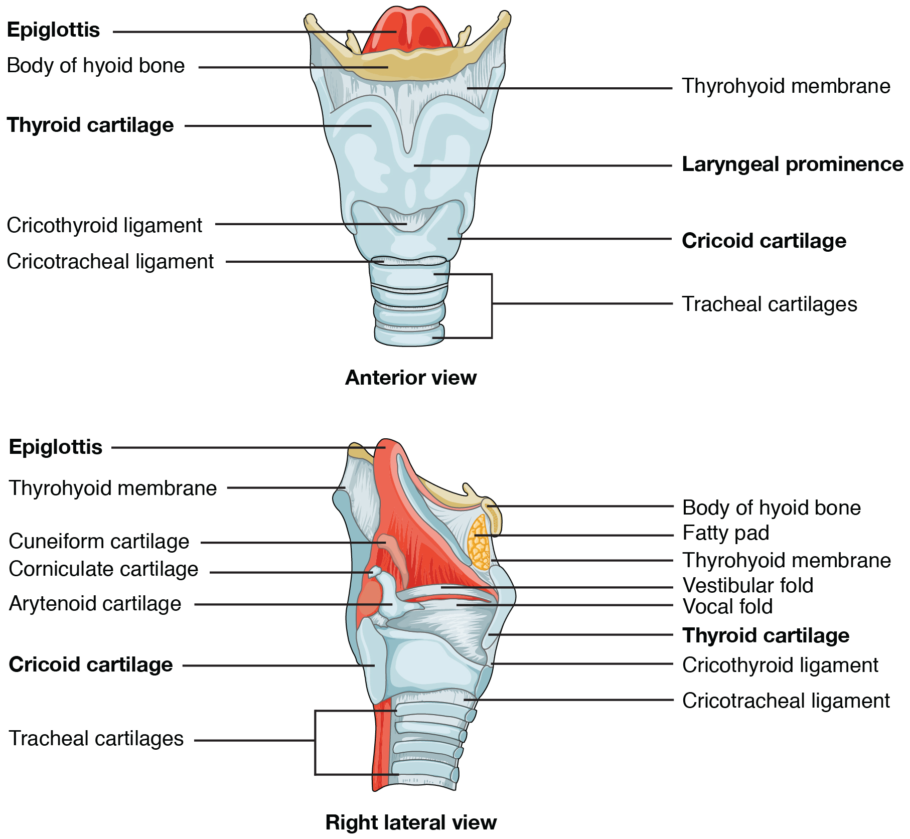
Locate the epiglottis, vocal folds, laryngeal cartilages and cricothyroid region. Relate the landmarks to airway anatomy in sedation and emergency assessment. Review tongue and pharyngeal obstruction in the accompanying lesson.
Larynx: anterior and right lateral views · OpenStax College (2013) · CC BY 3.0. Unchanged published image; displayed responsively. Original publication.
Electrical conduction system of the heart
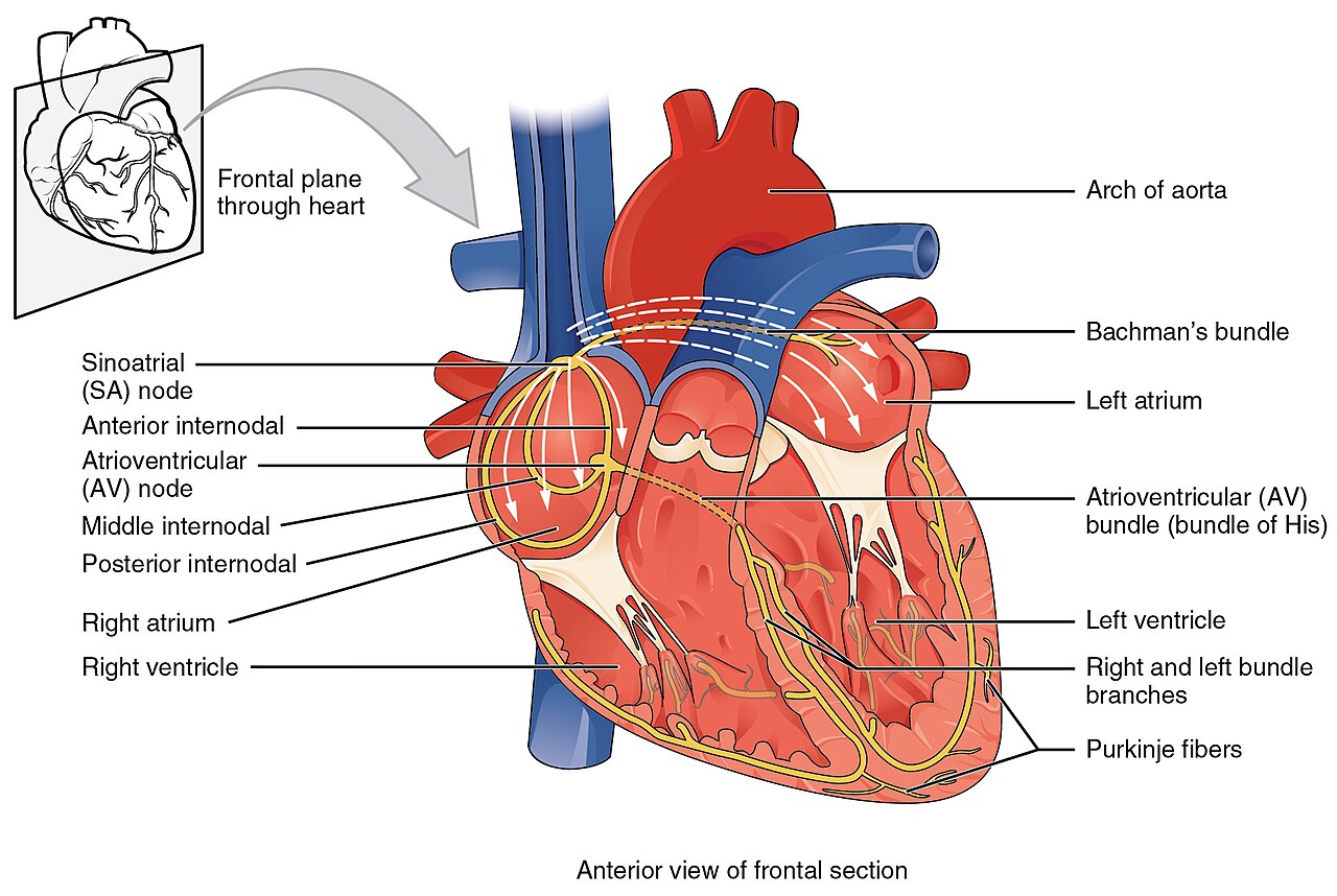
Trace conduction from the SA node through the AV node and His–Purkinje system. Connect electrical timing to the ECG and the cardiac-output discussion. Interpret a clinical rhythm from an ECG alongside the patient’s condition.
Electrical conduction system of the heart · OpenStax College (2013) · CC BY 3.0. Unchanged published raster preview; displayed responsively. Original available from the source. Original publication.
Superficial and deep veins of the upper limb
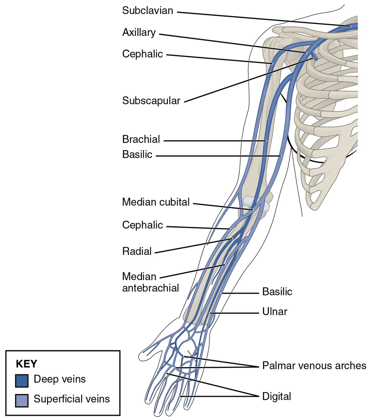
Identify cephalic, basilic, median cubital and median antebrachial veins. Use the colour key to distinguish superficial and deep drainage, and relate the anatomy to venous-access assessment. Individual superficial-vein patterns vary.
Superficial and deep veins of the upper limb · OpenStax College (2013) · CC BY 3.0. Unchanged published raster preview; displayed responsively. Original available from the source. Original publication.
No matching images
Try a shorter term, or clear the search to explore the full atlas.
Image credits and reuse
Each image has its author, source and licence beside it. Keep those details with the image when reusing it; share-alike terms apply where shown. Downloading an image does not include the caption automatically. Original labels and arrows are retained.