
Panoramic imaging
Read the whole image, including structures beyond the tooth of interest.
Quick revision summary
Interpret the projection before interpreting disease
Check patient positioning, symmetry, coverage and artefacts. The focal trough, variable magnification and superimposition affect the appearance of teeth and jaws.
Recognise positioning and superimposition
A panoramic image is built from a curved focal region rather than being a uniform photograph of the jaws. Structures outside the ideal plane can appear blurred or distorted.
Use a whole-image search sequence
Review the teeth and supporting bone, mandibular borders and canals, rami and condyles, maxillary structures and other visible areas in a consistent order. Compare sides while allowing for projection.
Common mistake
Panoramic magnification and superimposition prevent simple one-to-one interpretation of every apparent relationship.
Panoramic imaging and its limitations
Read the whole image, including structures beyond the tooth of interest.
Interpret the projection before interpreting disease
Check patient positioning, symmetry, coverage and artefacts. The focal trough, variable magnification and superimposition affect the appearance of teeth and jaws. Ghost images and air spaces can be mistaken for abnormalities. Positioning problems may make a region unreliable even when another part of the image appears sharp.
Use a consistent sequence through teeth, roots, supporting bone, mandibular borders and canals, condyles and the visible maxillary and adjacent structures. Describe a lesion’s site, margins, internal appearance and effects on nearby structures. A panoramic image gives a broad projection and cannot establish a three-dimensional relationship by itself. Additional local imaging or justified cross-sectional assessment may be needed if it changes care.
Mandibular landmarks
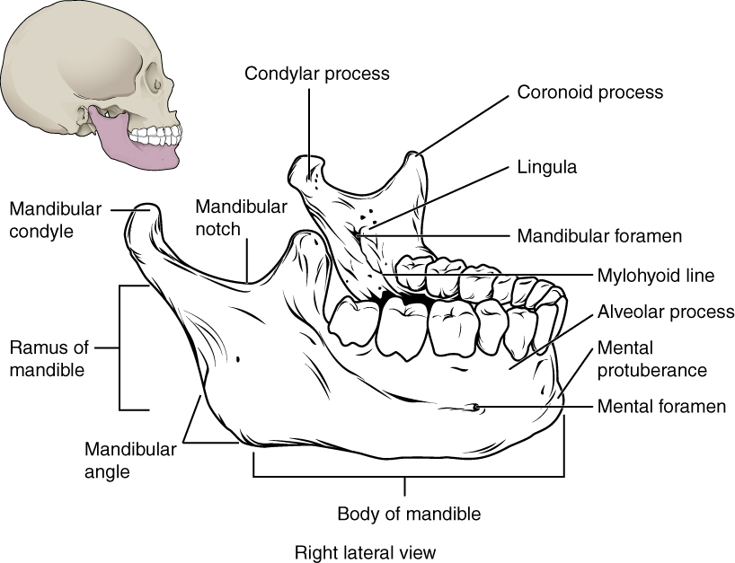
Locate the mental and mandibular foramina, lingula and mylohyoid line. The mandibular foramen, lingula and mylohyoid line are medial landmarks; this schematic brings several surfaces together. Relate the landmarks to nerve risk and fracture assessment.
Mandibular landmarks · OpenStax College · CC BY 3.0. Original image; displayed at a responsive size. Original publication.
Key distinctions in practice
| Finding or option | What it means | Clinical consequence |
|---|---|---|
| Focal trough | A zone of relatively sharp representation | Positioning affects which structures are reliable. |
| Magnification | Variable enlargement in projection | Do not assume exact measurements without an appropriate method. |
| Ghost / artefact | A projection effect or external object | Distinguish it from pathology through the pattern. |
| Whole-image report | All acquired areas require assessment | Avoid tunnel vision on the referral tooth. |
Panoramic anatomy with unerupted third molars
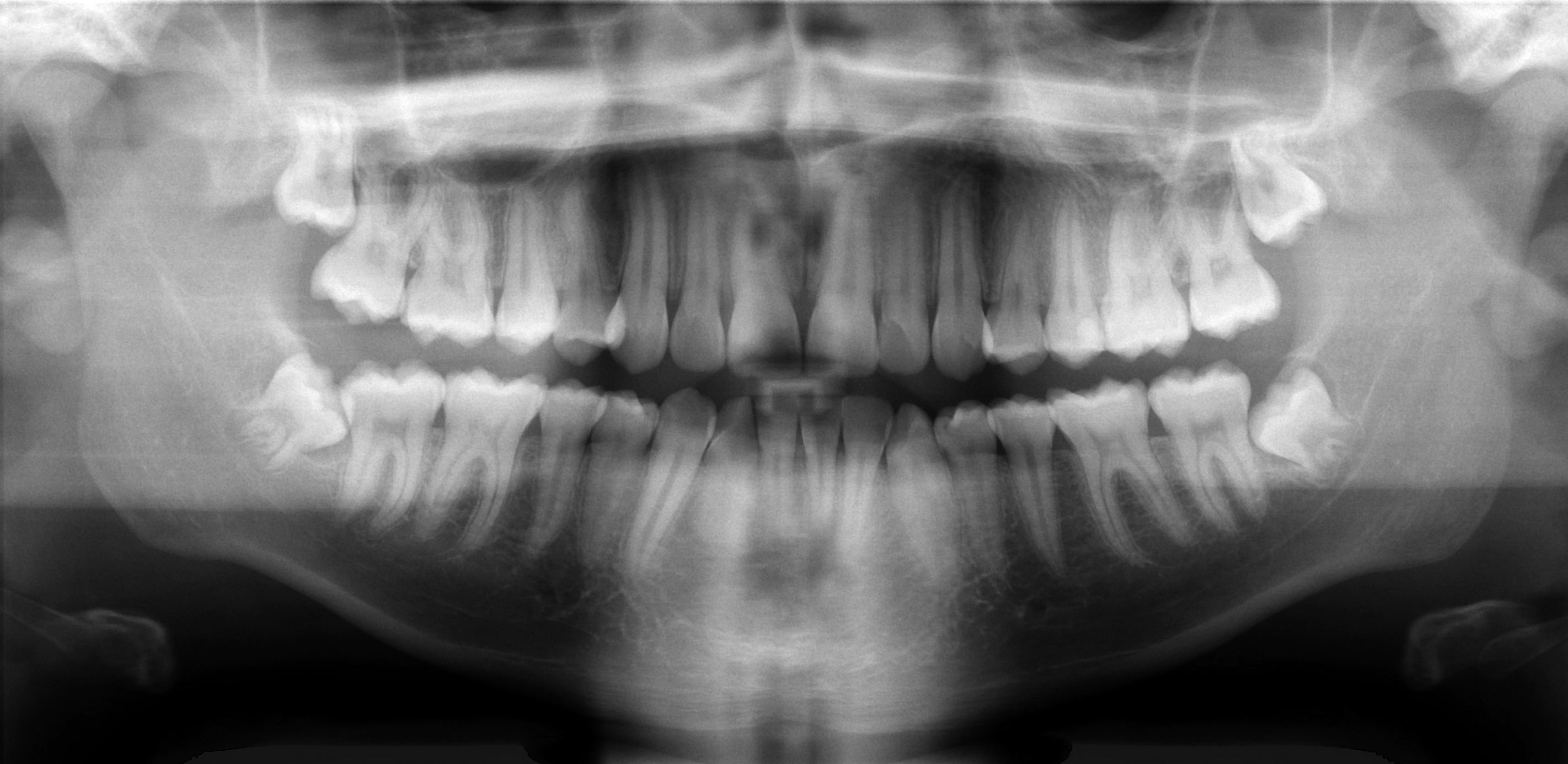
Scan the whole image systematically: compare both sides, trace the mandibular borders and canals, inspect the maxillary sinuses and count the teeth. This published example includes unerupted third molars; it is not an all-normal reference. Radiographic overlap alone cannot establish the three-dimensional nerve–root relationship.
Basic panoramic radiograph.jpg · Coronation Dental Specialty Group · CC BY 3.0. None; original image reproduced without alteration.
Can a panoramic image alone prove whether roots touch the inferior alveolar nerve?
No. It is a two-dimensional projection. Interpret the signs in clinical context, and request further imaging only when justified by a management question.
Recognise positioning and superimposition
A panoramic image is built from a curved focal region rather than being a uniform photograph of the jaws. Structures outside the ideal plane can appear blurred or distorted. Unequal positioning may change apparent width or symmetry. The tongue’s position, spine and metallic objects can introduce obscuring shadows or artefacts.
Interpret apparent displacement or enlargement cautiously until image geometry has been considered. A ghost image may be displaced and distorted relative to the object that produced it. Fine caries or small apical abnormalities may be less clearly shown than on a suitable intraoral view. The broad coverage is valuable, but it does not make the image the best test for every dental question.
Mixed dentition on a panoramic radiograph
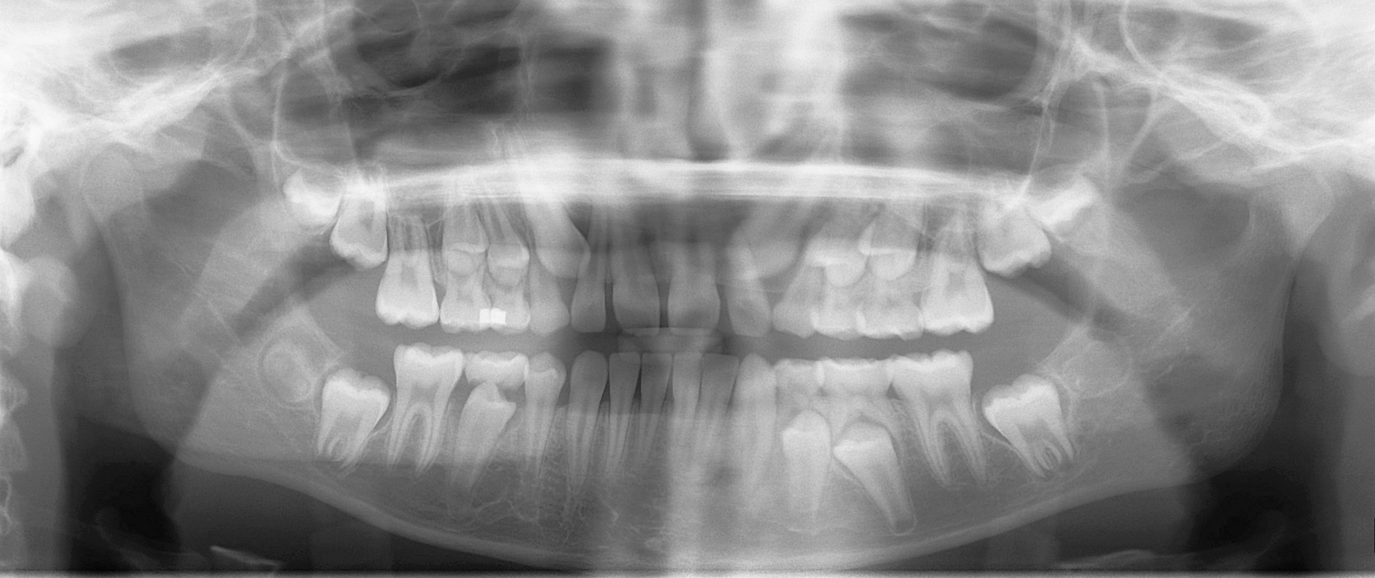
Distinguish erupted permanent teeth, retained primary teeth and unerupted successors. Compare development on the two sides and account for every permanent tooth. This is one published example of mixed dentition, not a fixed age-based template for every child.
Mixed dentition pan.jpg · Coronation Dental Specialty Group · CC BY 3.0. None; original image reproduced without alteration.
Which permanent teeth erupt without replacing primary teeth?
The permanent molars. Premolars replace the primary molars; permanent incisors and canines replace their primary predecessors.
Use a whole-image search sequence
Review the teeth and supporting bone, mandibular borders and canals, rami and condyles, maxillary structures and other visible areas in a consistent order. Compare sides while allowing for projection. For a lesion, record location, borders, density and effects on neighbouring structures before naming a likely diagnosis.
With an impacted third molar, inspect the relation to the mandibular canal and neighbouring tooth while still reviewing the remainder of the image. A projection cannot demonstrate every buccolingual relationship. Additional imaging is justified only if its answer could change care. Communicate an important incidental abnormality and allocate follow-up; it does not become irrelevant because it is distant from the referral’s original focus.
Dentigerous cyst: a pericoronal radiolucency
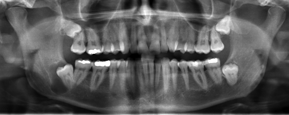
Locate the radiolucency associated with the impacted lower third molar on the left of the displayed image; the source describes a right mandibular dentigerous cyst. Assess its border and relationship to the crown, adjacent roots and mandibular canal. A pericoronal radiolucency supports a differential; imaging alone cannot establish the lining or exclude other odontogenic lesions.
JawCyst.jpg · Coronation Dental Specialty Group · CC BY 3.0. Source image reproduced without alteration; any arrows or circles are part of the original.
Which tooth relationship makes a dentigerous cyst an important consideration?
A radiolucency surrounding the crown of an unerupted tooth. An enlarged follicle and other odontogenic lesions can resemble it, so clinical, radiographic and appropriate histological findings must be correlated.
Odontogenic keratocyst: a posterior mandibular example
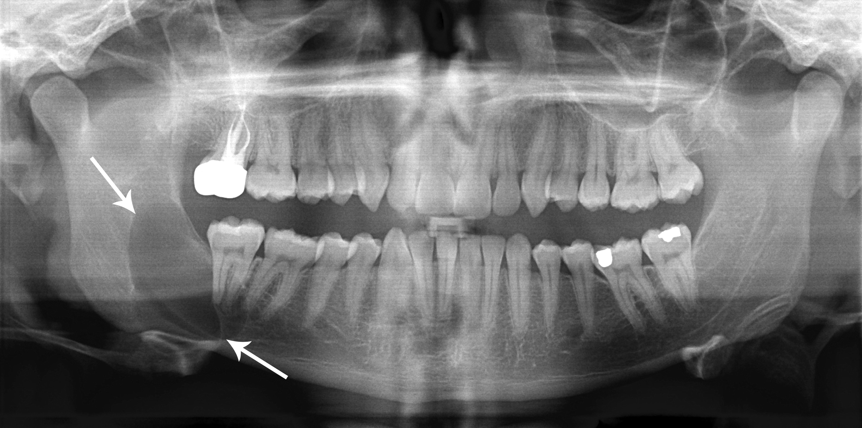
Use the original arrows to locate the posterior mandibular radiolucency and inspect its extent. The source diagnosis is an odontogenic keratocyst, described under the historical name “keratocystic odontogenic tumour”. Its relatively well-defined appearance does not make follow-up unnecessary. Other jaw lesions can look similar; definitive classification requires correlation with tissue findings.
Classic_keratocystic_odontogenic_tumour.jpg · Coronation Dental Specialty Group · CC BY 3.0. Source image reproduced without alteration; any arrows or circles are part of the original.
Can the relatively well-defined border distinguish this keratocyst from every other odontogenic cyst?
No. Borders and location help rank possibilities but overlap between lesions. The source diagnosis is supplied for teaching; it cannot be independently established from this panoramic image alone.
Stafne bone cavity: panoramic location
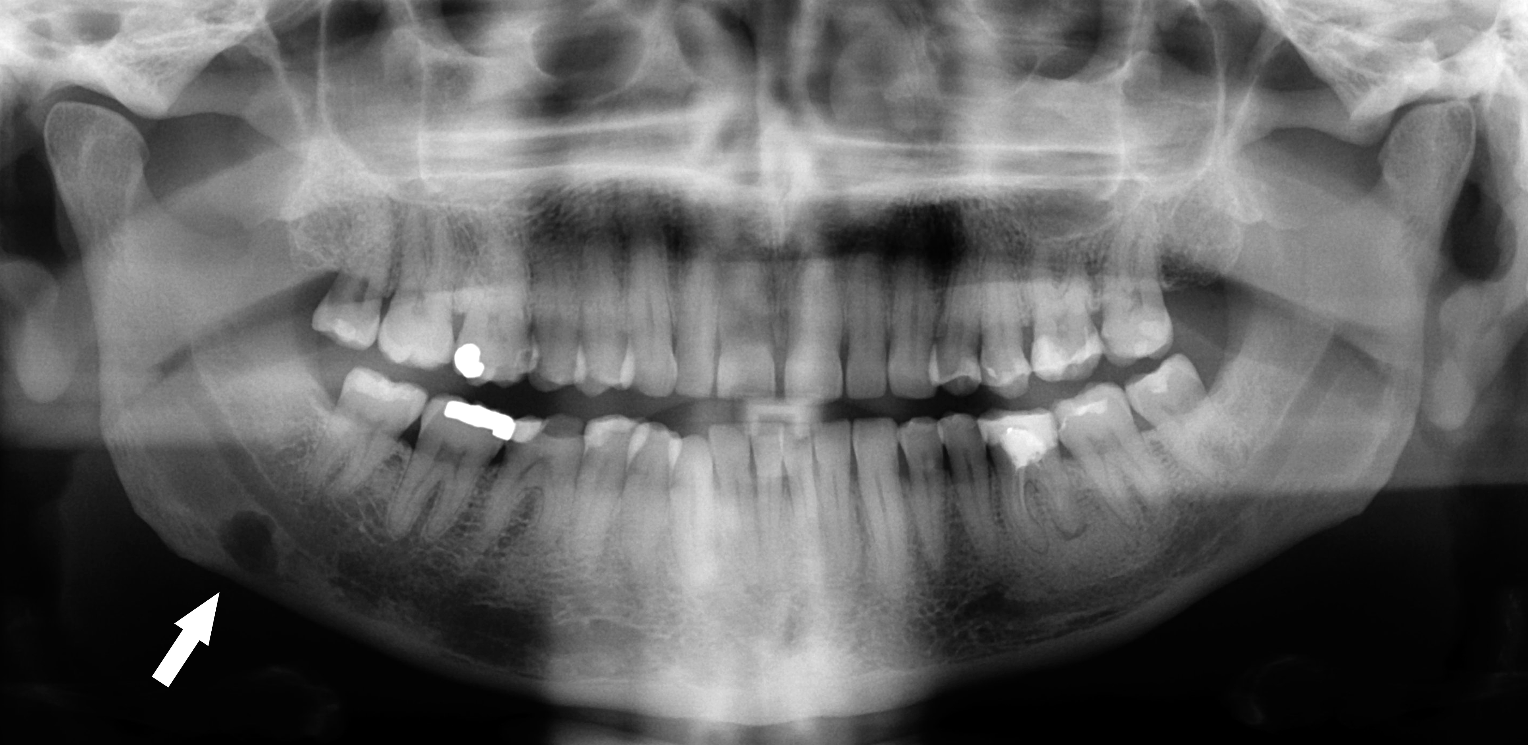
Follow the original arrow to the rounded radiolucency near the lower border of the right mandible, on the left of the displayed image. The source identifies a Stafne defect. Compare its position below the mandibular canal with the tooth-related relationships of odontogenic cysts. The axial CT shows the same source case from another plane.
Stafne defect panorex.jpg · Coronation Dental Specialty Group · CC BY 3.0. Reproduced without alteration. Labels, arrows and circles, where present, belong to the source image.
Which anatomical relationship is particularly helpful in this example?
Its location below the mandibular canal near the posterior lower border. Use the full pattern and clinical context; that relationship alone is not a universal rule for every radiolucency.
Mandibular body fracture: follow the cortex
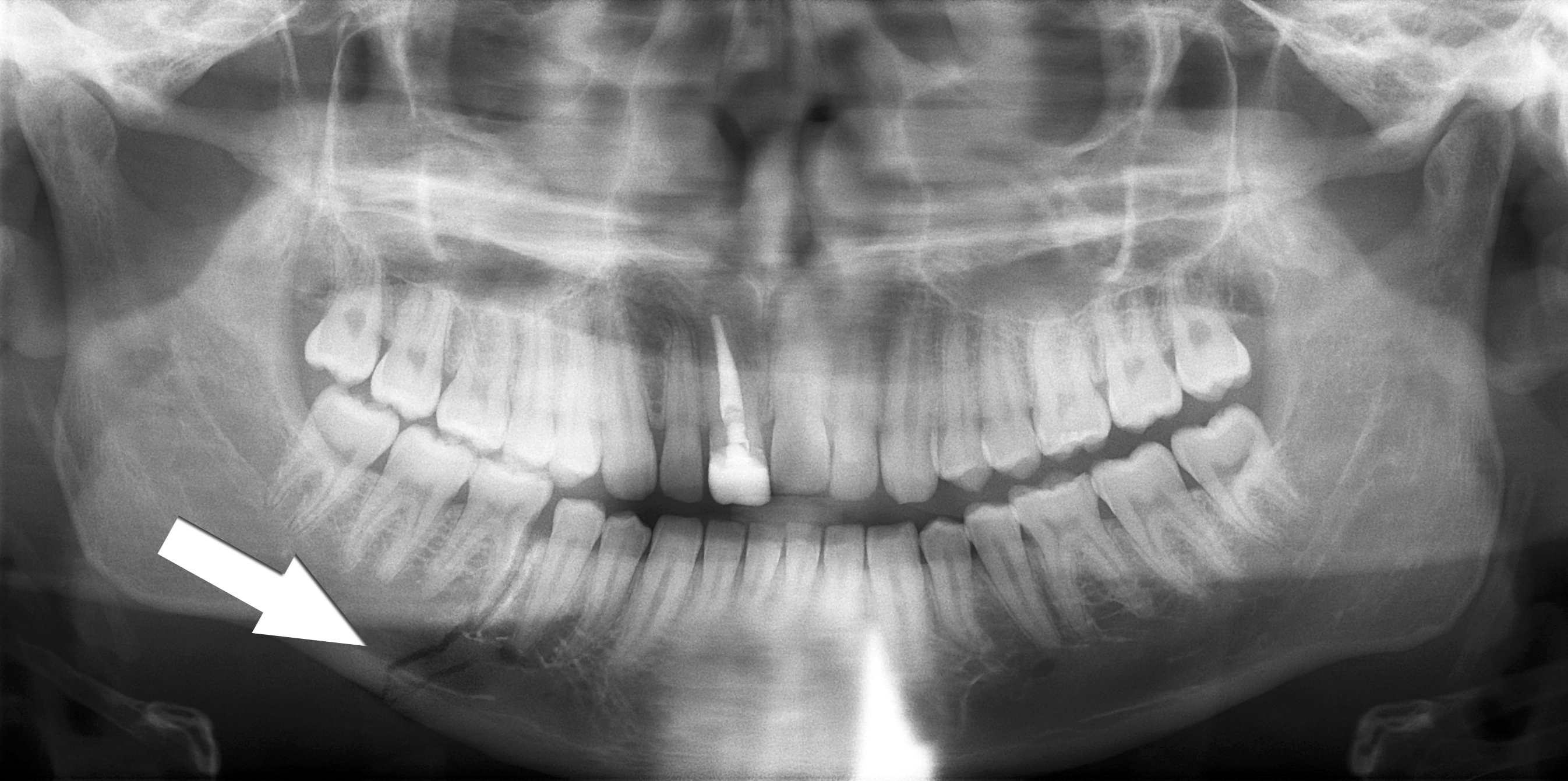
Trace the lower mandibular border through the fracture marked by the source arrow. Inspect the teeth and the remaining mandible as well as the marked site. The source describes a right body fracture. Clinical occlusion, soft tissues, sensation and the mechanism of injury remain part of the trauma assessment.
Simple mandible fracture.jpg · Coronation Dental Specialty Group · CC BY 3.0. Reproduced without alteration. Labels, arrows and circles, where present, belong to the source image.
Why should the search continue after finding the marked fracture?
Another fracture or associated injury may be present. Review the whole image and the patient’s clinical findings rather than stopping at the first abnormality.
Multiple mandibular fractures: inspect every region
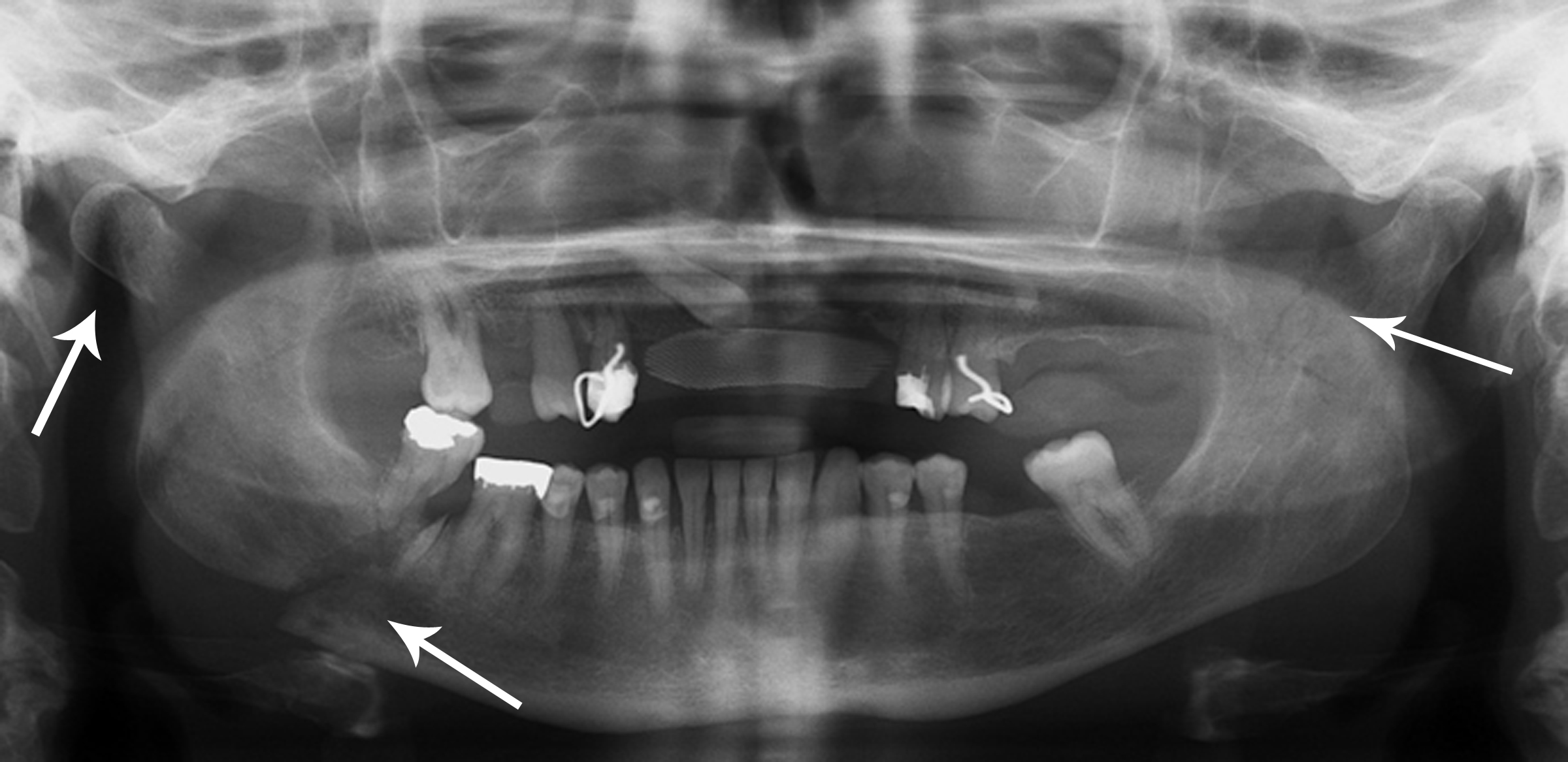
The source records right condylar and body fractures and a left coronoid fracture. Use the original arrows to orient the search, then trace each border systematically. A panoramic projection has overlap and positional limitations; a single teaching image cannot establish the complete injury pattern or its management.
Multiple mandible fractures.jpg · Coronation Dental Specialty Group · CC BY 3.0. Reproduced without alteration. Labels, arrows and circles, where present, belong to the source image.
Which clinical information is needed alongside the fracture pattern?
Airway and wider trauma assessment, occlusion, mouth opening, dental and soft-tissue injury, sensory findings and relevant patient factors, with additional investigations chosen for the clinical question.
A distinction to remember
Panoramic magnification and superimposition prevent simple one-to-one interpretation of every apparent relationship.
Why should a third-molar assessment include the rest of the panoramic image?
Reveal the reasoning
The whole acquired image requires interpretation. Important incidental findings can be missed by focusing only on the surgical tooth.
Guidance to read alongside this chapter
Test your recall
Why might a small early carious lesion be missed on a panoramic image?
Show answer
Its spatial resolution is lower than a suitable intraoral view.